Noby-448 Installation & Programming Instructions (Rev.5) Page 10 of 12
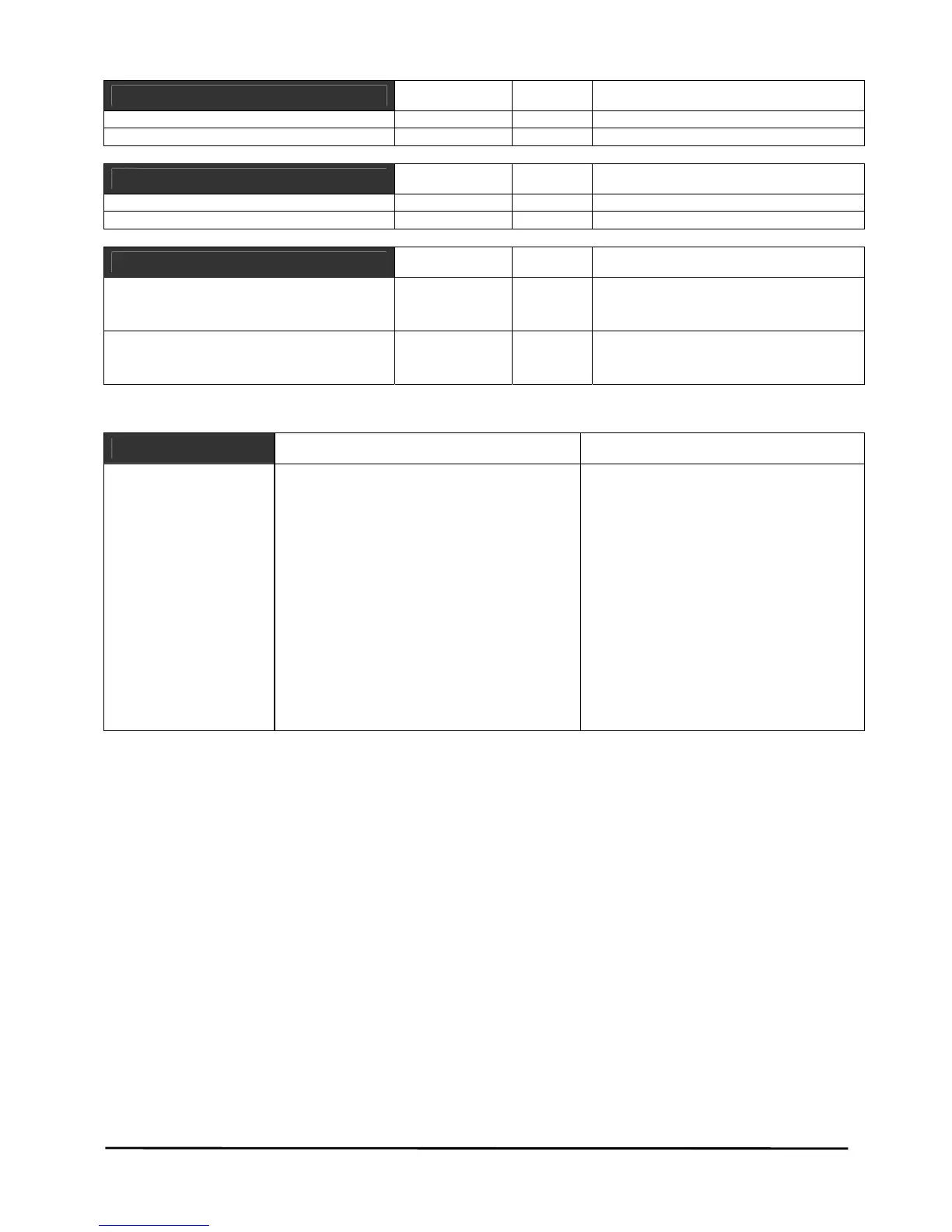
Communication Port (JP1)
Value Unit Comments
Zonal Outputs (JP1 pins 1 – 8) 10 mA 12volt +’ve going signal
Fault Output (JP1 pin 9) 50 mA 12volt open collector, +’ve going
Signal Inputs
Value Unit Comments
Class Change (Bell Ring “BR”) 200 kohm 12volt +’ve going signal (max 30v)
Fault Input (“Flt”) 200 kohm 12volt +’ve going signal (max 30v)
Cabinet
Value Unit Comments
Dimensions (width x height x depth):
• Main Panel
• Noby-448RKP Remote Keypad
335 x 325 x 75
220 x 110 x 55
mm
mm
1.2mm powder coated steel
1.2mm powder coated steel
Shipping Weight:
• Main Panel
• Noby-448RKP Remote Keypad
4.7
875
kg
g
LED Indications
Continuous Flashing
8 Zone Fire LED’s Zones alarmed First to alarm
Common Fire LED One or more zones in fire condition N/A
Zone Fault LED’s
(non-latching) **
Zone/s in fault
Zone/s isolated (slow flash)
Head Removed (intermittent ‘winking’)
Common Fault LED Any zone fault or system fault Fault Input terminal active, non-latching
Sounder Fault LED Sounder fault Sounders Isolated
PSU Fault LED Low voltage (< 21 volts), non-latching Fuses F1,F2,F7, Low volts & Battery
CPU Fault LED Remote Bus fault CPU watchdog warning
Power LED Primary supply (mains) OK. Off=mains fail Mains restored
Relay Isolate LED N/A Relay isolated
Function LED Access code successfully entered N/A
Isolate LED N/A One or more zones isolated
Test LED N/A 7 day fire test reminder
* * Zone Faults are non-latching as supplied from the factory. Latching function is a programmable option.