Noby-448 Installation & Programming Instructions (Rev.5) Page 9 of 12
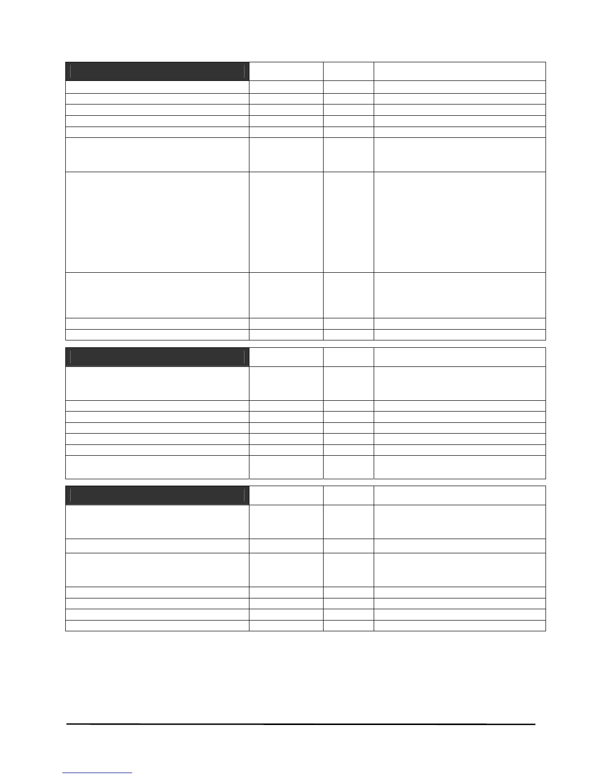
NOBY-448 SPECIFICATION
Power Supply Unit
Value Unit Comments
Mains Supply Voltage 230 +10% -6% volts AC
Mains Supply Frequency 50 / 60 Hz
Mains Power Rating 60 VA
Nominal Battery Voltage 24 volts
Regulated PSU charger voltage 27.3 volts
Regulated PSU charger current
• 20 minute rating
• continuous
2.5
2.0
A
A
Fused Outputs:
F1 Ext. Remote Bus & Aux 12v
F2 Aux 24v
F3 Sounder 1 Circuit
F4 Sounder 2 Circuit
F5 Sounder 3 Circuit
F6 Sounder 4 Circuit
F7 Battery +’ve
F8 30VAC Transformer Secondary
1.0
1.0
1.0
1.0
1.0
1.0
3.0
3.0
A
A
A
A
A
A
A
A
F1A 20mm Quick Blow
F1A 20mm Quick Blow
F1A 20mm Quick Blow
F1A 20mm Quick Blow
F1A 20mm Quick Blow
F1A 20mm Quick Blow
T3A 20mm Slow Blow
T3A 20mm Slow Blow
Standby Battery Current:
• Noby-448 4 zone main panel
• Noby-448 4+4 (Noby-448XT fitted)
• RKP Remote
70
105
25
mA
mA
mA
4 zone + 4 sndr EOL resistors fitted
8 zone + 8 sndr EOL resistors fitted
all LED’s off
Low Voltage Monitor 21.0 volts
Battery Capacity Monitor Yes 10s load test every 12hrs
Zone Circuits
Value Unit Comments
Detection Zones:
• Noby-448
• Noby-448 + Noby448XT module
4
8
No. Detectors Per Zone 20 based on 100uA per detector
End Of Line (EOL) Resistor 4700 ohms
Open Circuit Monitoring R > 10,000 ohms
Short Circuit Monitoring R < 100 ohms
Fire Alarm Detection 100 < R< 1600 ohms
Head Removal Monitoring Yes
• requires schottky diode bases
• sampled at 60s intervals
Sounder Circuits
Value Unit Comments
Sounder Circuits:
• Noby-448
• Noby-448 + Noby448XT module
4
8
Maximum No. Sounders Per Circuit 50 based on 20mA per sounder
Maximum No. Sounders – All Circuits:
• Noby-448
• Noby-448 + Noby448XT module
62
124
based on 20mA per sounder
based on 20mA per sounder
End Of Line (EOL) Resistor 4700 ohms
Open Circuit Monitoring > 10,000 ohms
Short Circuit Monitoring < 100 ohms
Fire Alarm DPDT Relay 1.0 A rated at 1.0A/30Vdc per contact set