Nokia FastMile 4G Receiver Product Overview
Issue: 01 DRAFT 3TG-00386-ABAA-TCZZA 47
DRAFT
Figure 11 Location of physical interfaces on the Compact mono-band and ABA models of the
Nokia FastMile 4G Receiver
28797
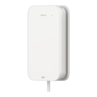
8.2 Physical interfaces of the Compact multi-
band models
Table 8 describes the physical interfaces of Compact multi-band models of the Nokia
FastMile 4G Receiver.
Table 8 Physical interfaces of the Compact multi-band models of the Nokia
FastMile 4G Receiver
Point for connecting to external ground
Located on the back of the unit; see Figure 12.
The Compact multi-band models have a female RJ 45 connector for attaching a
customer-supplied cat5e shielded Ethernet cable with standard pinouts that is a
maximum of 80 m (262 ft) in length; the same cable is also used for power (PoE as
per IEEE802.3 at type-2).
Located on the underside of the unit; see Figure 13.
Single multifunction LED that indicates status information for the Nokia FastMile 4G
Receiver.
Located on the top of the unit.
See section 10.1 for a figure showing the location of the status LED of the Compact
multi-band models and information about its behavior.
The Compact multi-band models have a set of five LEDs that work together to indicate
the LTE signal strength detected by the Nokia FastMile 4G Receiver.
Located on the top of the unit.
See section 10.2 for a figure showing the location of the signal strength LEDs and
information about their behavior.
Button to activate the signal strength LEDs
Located on the side of the unit.
See section 10.2 for a figure showing the location of the measurement button and
information about using it to activate the signal strength LEDs.
(1 of 2)
Physical interfaces