Do you have a question about the Nokia 515 RM-953 and is the answer not in the manual?
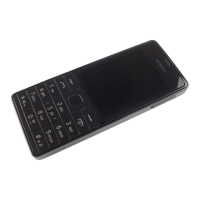
Prepare tools, protect device, remove B-COVER and BATTERY.
Separate A-COVER, remove KEYMAT, D-COVER, and DOME SHEET.
Disconnect DISPLAY, remove EARPIECE, CAMERA, and SPEAKER modules.
Remove SIM2 CONNECTOR, ANTENNA MODULE, and LED FLASH.
Install ANTENNA MODULE, then slide and secure the DISPLAY.
Attach KEYMAT to A-COVER and fasten internal screws.
Secure components by attaching clips and tightening screws to specified torque.
CA-101 Service cable and AC-20 Travel charger for connectivity and power.
SS-276 Camera removal tool and Nokia Standard Toolkit (v2) for disassembly/assembly.
Diagram illustrating device flashing using service software and cable.
| Model | Nokia 515 RM-953 |
|---|---|
| Network Technology | GSM / HSPA |
| 2G bands | GSM 850 / 900 / 1800 / 1900 |
| GPRS | Yes |
| EDGE | Yes |
| Announced | 2013, August |
| Dimensions | 114 x 48 x 11 mm (4.49 x 1.89 x 0.43 in) |
| Weight | 101.1 g (3.56 oz) |
| Type | TFT, 256K colors |
| Resolution | 240 x 320 pixels, 4:3 ratio (~167 ppi density) |
| Protection | Corning Gorilla Glass 2 |
| Memory Card slot | microSD, up to 32 GB |
| Phonebook | Yes |
| Call records | Yes |
| Internal | 256 MB |
| Video | 480p@30fps |
| Loudspeaker | Yes |
| 3.5mm jack | Yes |
| WLAN | No |
| Bluetooth | 3.0, A2DP |
| GPS | No |
| USB | microUSB 2.0 |
| Browser | WAP 2.0/xHTML, HTML |
| Games | Yes |
| Java | Yes, MIDP 2.1 |
| Music play | Up to 50 h |
| Colors | Black, White |
| Speed | HSPA |
| Status | Available |
| SIM | Single SIM (Mini-SIM) or Dual SIM (Mini-SIM, dual stand-by) |
| Size | 2.4 inches |
| Primary Camera | 5 MP |
| Camera Features | LED flash |
| Alert types | Vibration; MP3 ringtones |
| Radio | FM radio |
| Messaging | SMS, MMS, Email, IM |
| Battery | Li-Ion 1200 mAh |