Training and Vendor Development
CMO Operations & Logistics
Multimedia Creation & Support CONFIDENTIAL
28.Apr.2006
13
Service Manual E70 RM-10 / RM-24
Copyright © 2006 NOKIA Corporation. All rights reserved.
Approved 2.0
MGR
Page
(20)
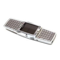
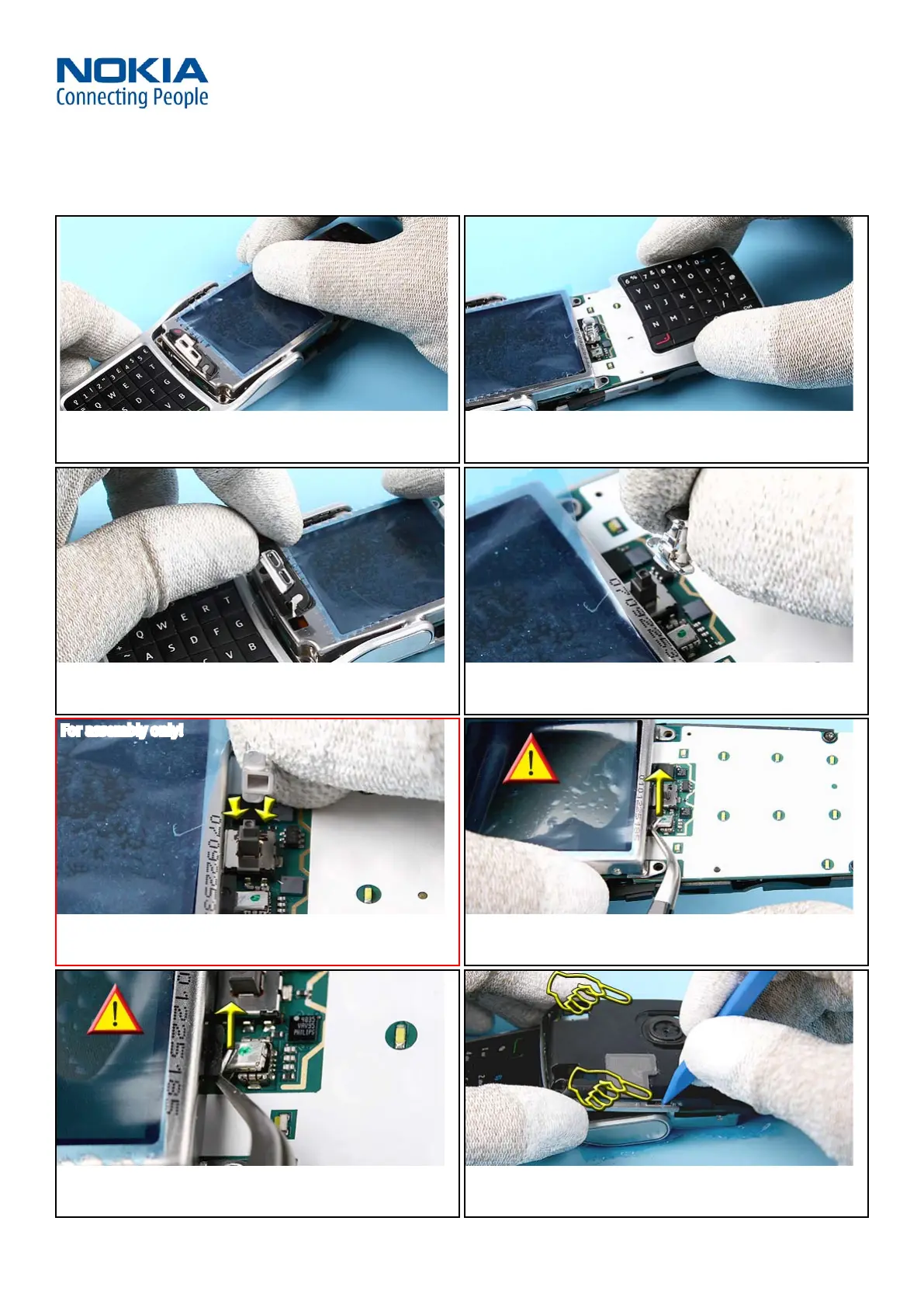
9. Cover the LCD MODULE with a protective lm. 10. Remove the ENGINE QWERTY KEYMAT.
11. Remove the POWER KEY. 12. Remove the JOYSTICK HAT.
13. Note the correct position when reassembling the JOYSTICK. 14. The FLIP HINGE is connected with the COAX CABLE to the ENGINE
MODULE.
15. Very gently, open the COAX CONNECTOR by using angled
tweezers.
16. The FLIP MODULE is attached to the B-COVER with two snaps.
For assembly only!
 Loading...