L1L2 Service Manual
Co nf id e nt ial | Cop yright © 2011 Nokia | A ll rights reserved
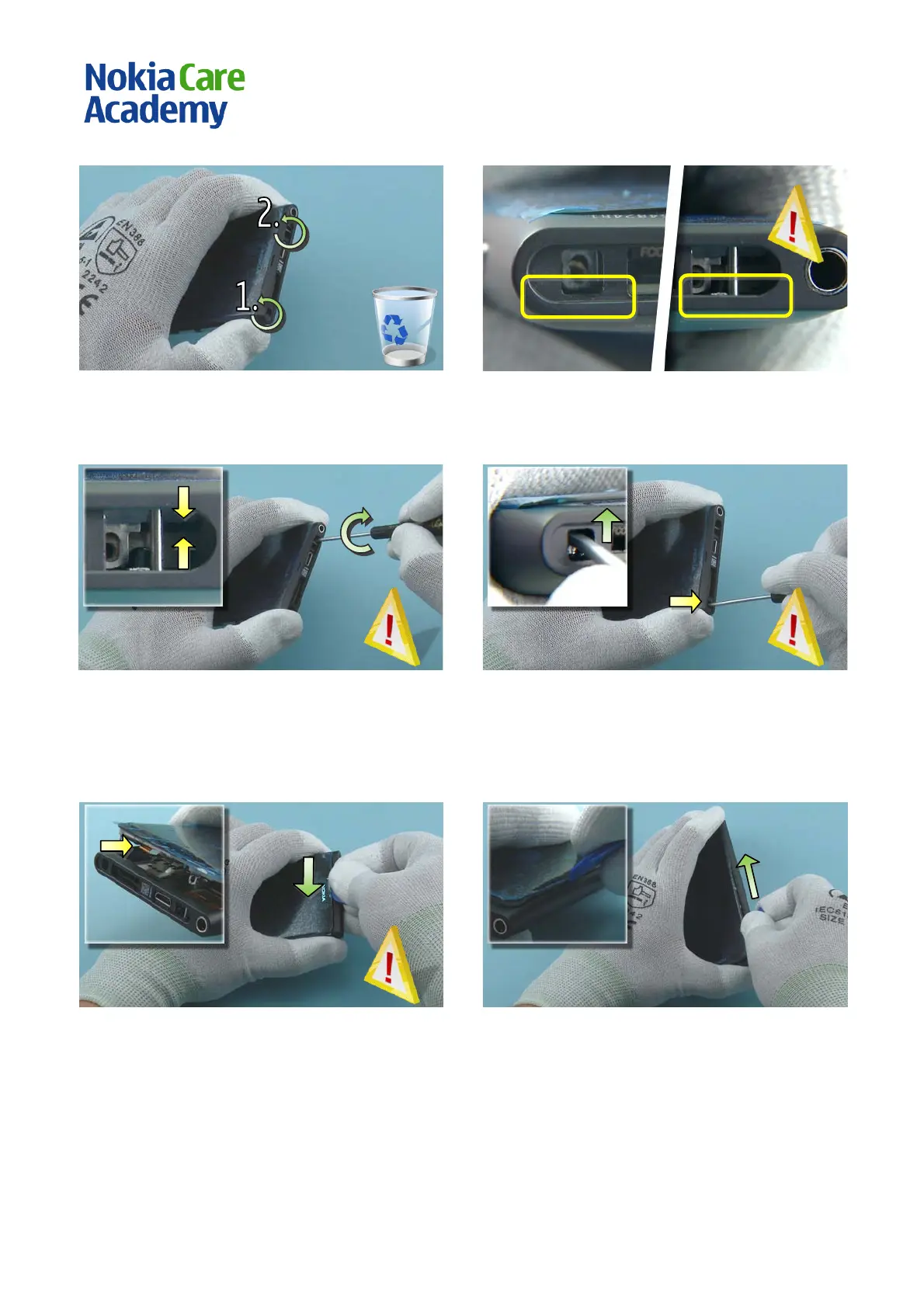
7) Unscrew the two Torx+ size 4 screws. Do not use
them again. Discard them.
8) When releasing the DISPLAY ASSEMBLY be very
careful not to damage the highlighted parts of the
PLASTIC BODY with the screwdriver!
9) Insert a flathead screwdriver in the shown hole on
the top side of the phone. Twist the screwdriver so
that the DISPLAY ASSEMBLY slightly rises out of the
PLASTIC BODY. Be careful not to damage the PLASTIC
BODY.
10) Insert a flathead screwdriver in the shown hole
and push it up to release the other side of the
DISPLAY ASSE MBLY. Be careful not to damage the
PLASTIC BODY.
11) Slide the SRT-6 along the top side of the phone,
between the DISPLAY ASSEMBLY and the PLASTIC
BODY. Be careful not to damage the shown flex
located halfway the top side.
12) Use the SRT-6 to open the left side of the DI SPL AY
ASS EMBLY.

 Loading...