RH-18/36/38 Company confidential
Engine module CCS Technical Documentation
Page 16 Nokia Corporation. Issue 1 10/03
Table 8: External microphone
Table 9: External speaker, differential output XEARP (HF) & XEARN (HFCM)
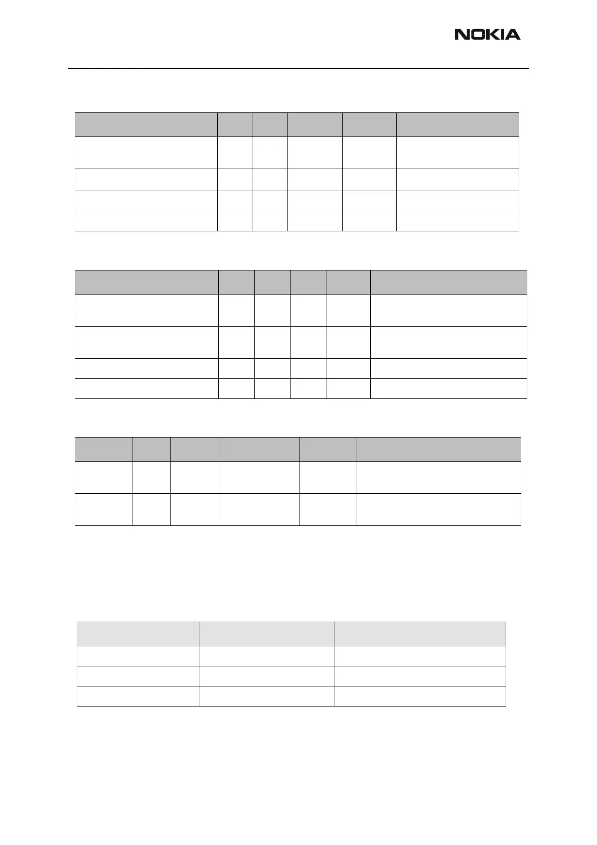
Table 10: Headset detection
Battery connector
Battery temperature is estimated by measurement in Transceiver PWB with a separate
NTC resistor. Thus the Battery Interface has only 3 contacts.
Table 11: Battery connector
Signal Min. Nom Max Condition Note
MIC2P (Differential input P) - - 100mV
pp
G=20dB 1,22kΩ to MIC1B (AC con-
dition)
MIC2N (Differential input N) - - 100mV
pp
G=20dB 1kΩ to GND
MICB2 (Microphone Bias) 2.0 V 2.1 V 2.25 V DC Unloaded
External loading of MICB2 - - 600uA DC
Signal Min. Nom Max Units Note
Output voltage swing*
* seen from transducer side
2.0 - - Vpp Differential output, with 60 dB sig-
nal to total distortion ratio
Common voltage level for
HF output (HF & HFCM) VCMHF
0.75 0.8 0.85 V
Load Resistance (HF to HFCM) 154 194 234 W 2×22Ω (±5%) + 150Ω (±25%)
Load Capacitance (HF to HFCM) - - 10 NF Load to GND
Signal Min. Nom Max Condition Note
HookInt 0V - 2.86V (Vflash1) Headset button call control, connected
to UEM AD-converter
HeadInt 0V - 2.86V (V flash1) Accessory detection, connected to
UEM AD-converter
Name Description Test usage
VBAT Battery voltage terminal. Battery calibration.
GND Battery ground terminal.
BSI Battery size identification. Flash and local mode forcing.