2
www.norcold.com
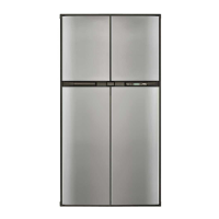
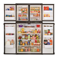
2118, 2118IM, 2118IMD Series
Contents
Safety .......................................................................................................... 3
Introduction .................................................................................................. 4
About This Manual .................................................................................. 4
Certification and Code Requirements ..................................................... 4
About Installation ..................................................................................... 4
Replacement Parts .................................................................................. 4
Technical Assistance ............................................................................... 4
Model Identification ................................................................................. 4
Cooling Unit Serial Number ..................................................................... 4
Refrigerator Model Number ..................................................................... 4
Specications .............................................................................................. 5
Exploded View ............................................................................................. 6
General Information ..................................................................................... 8
Ventilation ................................................................................................... 8
Overview ................................................................................................. 8
Enclosure ................................................................................................ 8
Baffles ..................................................................................................... 8
Lower Intake Vent .................................................................................. 8
Exhaust Vent ........................................................................................... 9
Roof Cap ................................................................................................. 9
Propane Gas Connections .......................................................................... 9
Leak Test-Detergent ................................................................................ 9
Leak Test-Compressed Air ...................................................................... 9
Electrical Connections ................................................................................. 9
120 Volts AC Electrical Connection ......................................................... 9
12 Volts DC Electrical Connection .......................................................... 9
Power Board Fuses ................................................................................. 9
Electrical Components .............................................................................. 10
Fresh Food Compartment Light ............................................................ 10
Divider Heater ...................................................................................... 10
12 Volt DC Fans ................................................................................... 10
Thermostatic Switch ............................................................................. 10
Movable Door Seal ............................................................................... 10
Replacement Fuse Size ........................................................................ 10
Temperature Monitor Control (TMC) ......................................................11
Preventative Maintenance ..........................................................................11
Gas Flame Appearance ............................................................................. 12
Remove and Clean the Burner Orice ...................................................... 12
Controls ..................................................................................................... 12
Power ON / OFF Button ........................................................................ 12
Mode Button .......................................................................................... 13
Temperature Set Button ........................................................................ 13
Temperature Indicator ........................................................................... 13
Gas Operation ....................................................................................... 13
Modes of Operation ................................................................................... 14
Gas Mode .............................................................................................. 14
AC Mode ............................................................................................... 14
Lighting Instructions .................................................................................. 14
Test the Gas Safety Valve ......................................................................... 14
Diagnostic Pre checks ............................................................................... 14
Fault Codes .............................................................................................. 15
Blank Display ........................................................................................ 15
no AC .................................................................................................... 17
no FL ..................................................................................................... 17
FL -- ....................................................................................................... 17
no AC, no FL ......................................................................................... 18
AC rE ..................................................................................................... 18
AC HE ................................................................................................... 18
oP LI ...................................................................................................... 18
Figures
Fig. 1 - Double-wrenching gas fittings ..................................................... 3
Fig. 2 - Cooling unit bar code label location. ........................................... 4
Fig. 3 - Refrigerator information label location ....................................... 4
Fig. 4 - Exploded front view .................................................................... 6
Fig. 5 - Exploded rear view .................................................................... 7
Fig. 6 - Typical roof exhaust venting ..................................................... 8
Fig. 7 - Thermostatic switch for fans. .................................................... 10
Fig. 8 - Movable door seal. .................................................................... 10
Fig. 9 - Temperature monitor control ......................................................11
Fig. 10 - Burner Box Location .............................................................. 12
Fig. 11 - Burner/Orifice Assembly ......................................................... 12
Fig. 12 - Control Locations ................................................................... 12
Fig. 13 - Mode Indicators ..................................................................... 13
Fig. 14 - Continuous 12 Volts ............................................................... 15
Fig. 15 - Switched 12 Volts ................................................................... 16
Fig. 16 - Magnet position ....................................................................... 22
Fig. 17 - Wiring Diagram ...................................................................... 29
Fig. 18 - Wiring Pictorial ........................................................................ 30
Fig. 20 - 2118 upper rear wiring ............................................................ 31
Fig. 21 - 2118 lower rear wiring ............................................................ 31
Fig. 23 - 2118IM lower rear wiring ......................................................... 32
Fig. 22 - 2118IM and 2118IMD upper rear wiring .................................. 32
Fig. 24 - 2118IMD lower rear wiring ...................................................... 33
Temperature Monitor Control (TMC) - Red Light Flashing .................... 20
Temperature Monitor Control (TMC) - Red Light on Solid ..................... 21
Clear the Temperature Monitor Control (TMC) Lockout State ............... 22
Sr ........................................................................................................... 23
Lo dc without alarm ............................................................................... 23
Lo dc without alarm while in GAS Mode ............................................... 23
Lo dc with alarm .................................................................................... 23
dr ........................................................................................................... 24
Flashing temperature setting icon ......................................................... 24
Diagnostic Mode ........................................................................................ 25
Access Diagnostic Mode ....................................................................... 25
Change Screens ................................................................................... 25
Exit Diagnostic Mode ............................................................................ 25
Screens and Diagnostic Segments Information .................................... 25
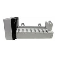
Ice Maker ................................................................................................... 28
Wiring Diagram .......................................................................................... 29
Wiring Pictorial .......................................................................................... 30
2118 Rear Wiring Views ............................................................................ 31
2118IM and 2118IMD Rear Wiring Views .................................................. 32
Remove / Replace the Refrigerator ........................................................... 34
Remove the Refrigerator ....................................................................... 34
Replace the Refrigerator ....................................................................... 34
FRENCH AND SPANISH TEXT BEGINS ON PAGE 35.