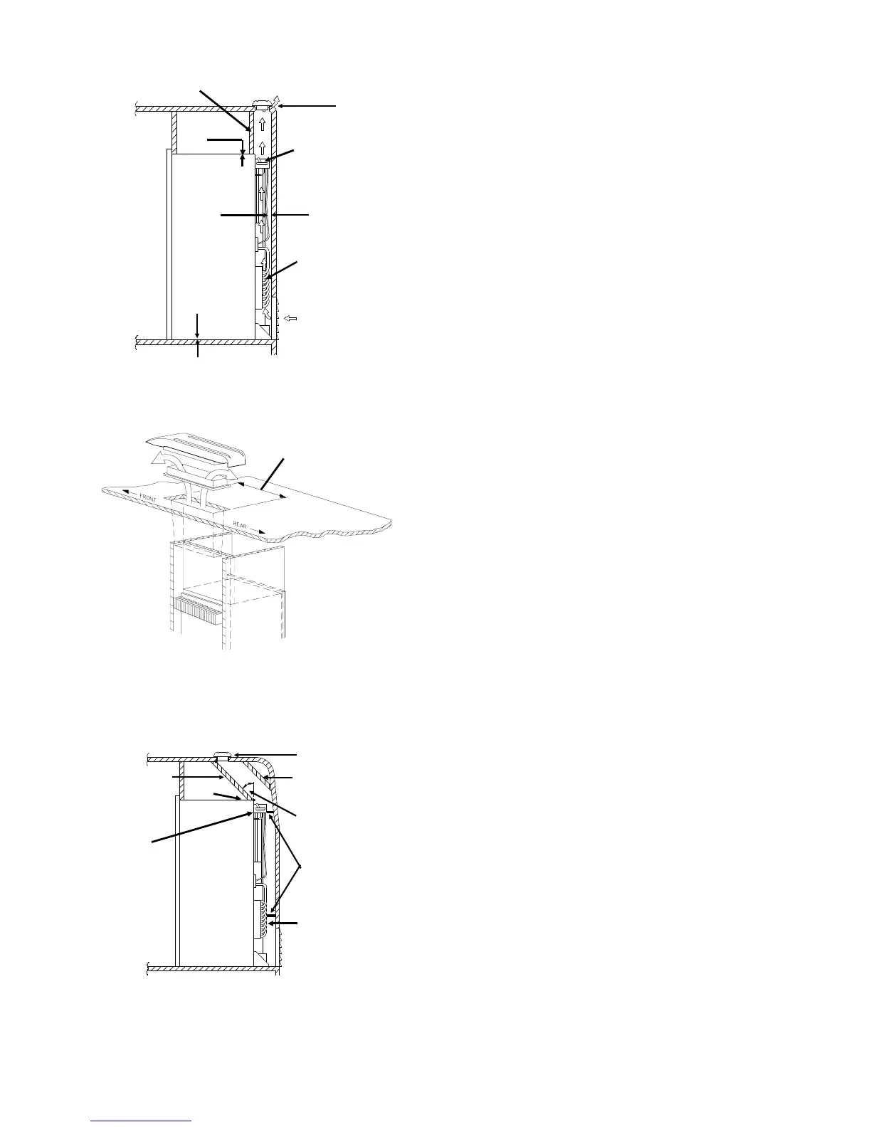
Optimum Installation - Figure 1
The optimum installation is illustrated in Fi
ure 1.
1. Area above refri
erator blocked
baffled
off to
prevent trappin
of hot air above the refri
erator.
2. 0 -1/4 inch clearance at the top of the refri
erator.
3. Exhaust vent centered directl
over refri
era-
tor’s condenser.
4. 0 - 1 inch at rear of the refri
erator.
5. 0 inch clearance at bottom of refri
erator.
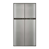
Exhaust Vent Centered - Figure 2
Fi
ure 2 further illustrates the re
uirement to center
the exhaust vent openin
over the condenser of the
refri
erator.
.
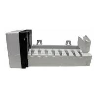
Alternate Construction Requirements
Figure 3
1. Exhaust vent openin
is inboard in relation to
the rear of the refri
erator.
2. Baffles added to the top of the refri
erator to
assist in directin
air flow out the exhaust vent.
3. 0-1/4 inch clearance at the top of the refri
erator.
4. An
le between baffles and rear top ed
e of the
refri
erator not to exceed 45 de
rees.
5. Deflectors added at rear in strate
ic locations
ad
acent to the coolin
units condenser and ab-
sorber coils to reduce clearance to 0 to 1 inch.
4
5
3
Condenser
source of
re
ected heat
Absorber
source of
re
ected heat
Air flow path
1
2
Fi
ure 1
5
Absorber
1
2
4
Condenser
2
3
Fi
ure 3
Exhaust vent openin
centered over condenser
front to rear of vehicle
Fi
ure 2
6