EasyManua.ls Logo

Norcold 9162 User Manual

Norcold 9162
36 pages
To Next Page IconTo Next Page
Page #1 background imageLoading...
Page #1 background image
900 & 9100
Series
Service Manual & Parts List
for Models
9182 9183
9162 9163
982 983
962 963
Contents
Safety Information . . . . . . . . . . . . . . . 1
Introduction . . . . . . . . . . . . . . . . . . . 2
Specifications . . . . . . . . . . . . . . . . . . 3
Operating Controls . . . . . . . . . . . . . . . 5
Operating Sequence . . . . . . . . . . . . . . 6
Alphanumeric Codes-900 Series . . . . . . . . 7
Flashing LEDs-9100 Series-
(Diagnostic Indicators) . . . . . . . . . . . . . 11
Diagnostics Fault Indicators-900 & 9100 Series 13
Step-by Step Trouble Shooting . . . . . . . . . 15
Internal Control Information - 900 Series . . . . 19
Internal Control Information - 9100 Series . . . 24
Diagnosing Cooling Problems . . . . . . . . . . 29
Component Check-Out Procedures . . . . . . . 31
Procedure for Cleaning Cooling System Flue . . 33
Fuse Replacement Procedure . . . . . . . . . 34
Wiring Pictorials . . . . . . . . . . . . . . . . . 35
618526C (96-05)

Other manuals for Norcold 9162

Question and Answer IconNeed help?

Do you have a question about the Norcold 9162 and is the answer not in the manual?
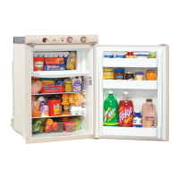
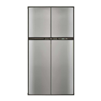
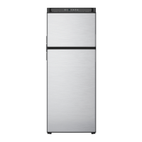
Norcold 9162 Specifications

General IconGeneral
TypeAbsorption Refrigerator
Depth24 inches
Temperature Range (Refrigerator)34°F to 40°F
RefrigerantAmmonia
Power SourceAC/DC/LP Gas
Capacity6.3 cu ft
Width23.5 inches
Energy Consumption1.5 kWh/day

Summary

General Safety Precautions

Safety Alert Symbol and Signal Words

Explains the Safety Alert Symbol, DANGER, WARNING, CAUTION signal words, and their meanings.

Key Safety Practices

Lists essential safety precautions for installation, servicing, and operation of the refrigerator.

900 Series Diagnostic Codes

LP Gas Ignition and Re-Ignition Faults (A1, A2)

Details codes A1 and A2 for LP gas ignition failures during start-up or operation.

AC and DC Voltage Faults (A5-A8)

Covers codes A5-A8 related to AC and DC input voltage being too low or too high.

Heater and System Faults (C1-C4)

Explains codes C1-C4 indicating burner ignition failure, DC heater failure, or open heaters.

System and Heater Output Faults (C5-C9)

Details codes C5-C9 related to backup systems, heater output faults, and out-of-tolerance conditions.

Inter Control Failure (d1)

Describes code d1, indicating a fault within the main control board itself.

9100 Series Flashing LED Indicators

LP Gas and AC Power Indicator Faults

Explains flashing LP Gas LED (ignition) and AC LED (power availability/voltage issues).

DC Voltage and Heater Faults

Explains flashing Battery LED (DC voltage issues) and all LEDs flashing (heater faults).

System Status and Heater Faults

Details flashing LEDs for backup system, AC heater faults, and DC heater faults.

Fault Indicator Summary and Actions

Troubleshooting Guide by Fault

Cooling System Diagnosis

Component Testing Procedures

Fuse Replacement Guide

Related product manuals