Further information on DC supplies can be found later in this
manual.
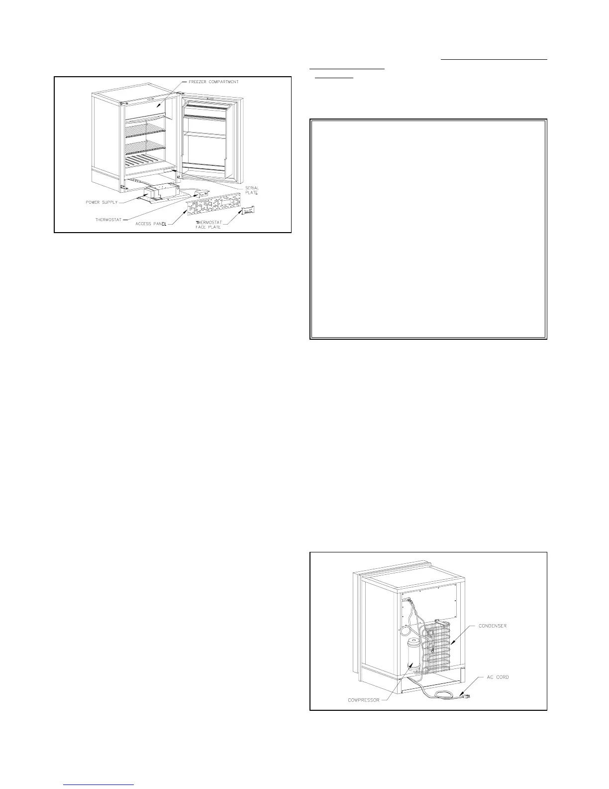
AC Power Connection
The 120 volt AC power connection is made b
connectin
the
refri
erator’s AC cord to a standard 120 volt
rounded receptacle.
See Fi
ure 2.
The 120 volt AC suppl
wires, to which the refri
erator is con-
nected, should be routed throu
h the fuse panel or circuit breaker
that protects the vehicle when an outside power source is used.
This connection should be permanentl
wired in accord-
ance with existin
overnin
codes. The use of an extension cord
is not recommended.
CAUTION:
IF AC POWER IS SUPPLIED BY AN ON-BOARD GENERATOR,
IT IS VERY IMPORTANT TO HOLD BOTH VOLTAGE AND FRE-
QUENCY WITHIN THE TOLERANCES STATED IN THE FRONT
OF THIS MANUAL
OPERATION
Power Source
As previousl
noted, the Norcold refri
erator can be operated on
either 12 volts DC or 120 volts AC. If both power sources are
connected simultaneousl
, the refri
erator will operate on 120
volts AC. A special rela
disconnects the DC power. To operate
on DC power, the AC source must be disconnected, allowin
the
rela
to switch to 12 volts DC.
On DC operation the circuit is protected electronicall
for over-
current and overvolta
e. Likewise on AC operation the circuit is
protected from overload conditions b
a bi-metallic current limitin
device.
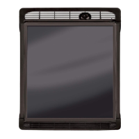
Temperature Control
A sin
le thermostat controls the operation of the refri
erator on
AC or DC. It is located on the panel below the front door
See Fi
.
1
. The dial is marked "1" throu
h "5". The nearer the dial is set to
"5", the colder the temperature becomes in the cabinet.
There is no need to read
ust the settin
of the thermostat for
dual operation. Once the desired temperature is reached, the
thermostat will control the cabinet temperature e
uall
well on
either volta
e suppl
.
Initial Start-up
Before operatin
the refri
erator for the first time, check to see
that the AC and DC suppl
connections are correct. If normal, the
reen power indicator will be illuminated. Connect the vehicle to
the external power suppl
of 120 volts. Turn the switch located
next to the thermostat to the "ON" position. Turn the thermostat
dial to the number "3" settin
. The unit should be operatin
. You
can hear the compressor sound b
placin
our ear next to the
refri
erator.
Allow approximatel
five minutes of operation and open the
freezer compartment door. Place
our hand at the upper left rear
corner of the coolin
plate. This is the area of the plate that will
be
in coolin
first. If
ou notice a coolin
effect at this point, then
the unit is functionin
properl
.
Close the refri
erator door and allow the refri
erator to operate
on AC until it c
cles or shuts itself off. This indicates the thermo-
stat is operatin
and that the refri
erator is coolin
on AC opera-
tion.
Now, disconnect the AC suppl
and open the refri
erator door so
that the cabinet interior will warm up and allow the thermostat to
demand coolin
.
As soon as the unit’s compressor be
ins to operate, close the
refri
erator door, allowin
the unit to run. It should shut off or c
cle
within 10 to 20 minutes indicatin
the DC operation is correct.
Special Requirements For
Marine Installations:
The DE-704D is internall
wired so that the AC and DC
circuits are isolated from each other. If the positive
+12 volts
DC input is
rounded in an
wa
cuts in the wire insulation,
improperl
insulated connections, etc.
, a volta
e potential
could be developed throu
hout the boat in which corrosion
develops on an
metal parts exposed to water.
This situation ma
be avoided b
wirin
the boat so that AC
and DC
rounds are common and wirin
is protected per
NNMA CERTIFICATION HANDBOOK
1987
. Inspect all wir-
in
to insure that insulation has not been dama
ed. Plastic
wire clamps are recommended.
To obtain more information on corrosion, a
ood reference
is:
BOAT AND YACHT CORROSION CONTROL
b
Yacht Corrosion Consultants, Inc.
2368 Eastman Ave. #6, Ventura, Ca. 93003.
Figure 2
Figure 1
4
 Loading...