SERVICE MANUAL
7
www.norcold.com
Troubleshooting, Cont'd
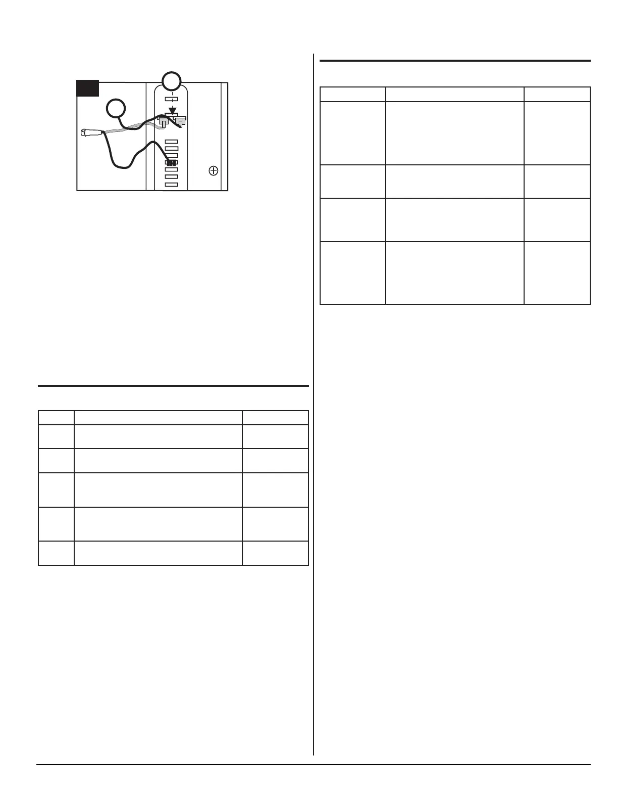
5. Connect the 12 VDC input wire (C) to the other side of adapter
blade
(B).
Fig. 3.5 - LED connection to control module
Reading the LED
If an error code is activated in the control module and the LED is
connected, it will fl ash a number of times. The number of fl ashes
will depend on what error was recorded. Each fl ash will last 1/4
second and after the code is fl ashed there will be a delay, then the
code will repeat.
Write down all error codes; then refer to "Self-Test Diagnostic
Chart" below.
Self-Test Diagnostic Chart
Flashes Description Action
1 Battery Protection Cut-Out.
The voltage is outside the cut out setting.
Perform Test A.
2 Fan Over current Cut-Out.
The fan electrical load is more than 1.0 amp.
Perform Test B.
3 Motor Start Error.
The rotor is blocked or the differential pressure in the
refrigeration system is too high ( >5 bar).
Perform Test C.
4 Minimum Motor Speed Error.
The motor can not maintain minimum speed (1850
rpm).
Perform Test D.
5 Thermal Cutout of Electronic Unit.
The electronic unit is running too hot.
Perform Test E.
5
NOR000019A-5c
C
B
Diagnostic Symptom Chart
Problem Possible Cause Action
Refrigerator Not
Cooling, Not
Turning On.
■ Faulty thermostat.
■ Faulty power to control module.
■ Broken wire from module to compres-
sor.
■ Faulty control module.
■ Faulty compressor.
Perform Test F.
Refrigerator Gets
Too Cold.
■ Bad capillary tube position.
■ Faulty thermostat.
■ Faulty control module.
Perform Test G.
Refrigerator Builds
Frost Inside.
Outside air entering refrigerator due to:
■ Door not closed.
■ Damaged door gasket.
■ Air leak around foam plug.
Perform Test H.
Refrigerator Runs,
But Does Not Cool
Properly.
■ High ambient temperatures.
■ Blocked air ventilation.
■ Frost build up.
■ Condenser coil restricted.
■ Faulty condenser fan.
■ Faulty cooling unit.
Perform Test I.



 To Next Page