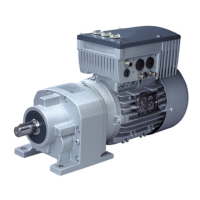
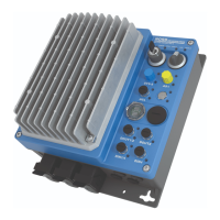
NORDAC PRO (SK 500P) – Users Manual for Frequency Inverters
4 BU 0600 en-2319
Table of Contents
1 General ......................................................................................................................................................... 8
1.1 Device characteristics ........................................................................................................................ 9
1.2 Delivery ............................................................................................................................................ 12
1.3 Scope of delivery.............................................................................................................................. 12
1.4 Safety, installation and operating instructions .................................................................................. 16
1.5 Explanation of markings ................................................................................................................... 20
1.6 Warning information on the product ................................................................................................. 21
1.7 Standards and approvals ................................................................................................................. 22
1.7.1 UL and CSA approval ......................................................................................................... 22
1.8 Type code / nomenclature ................................................................................................................ 23
1.8.1 Type plate ........................................................................................................................... 23
2 Assembly and installation ........................................................................................................................ 25
2.1 Frequency inverter installation ......................................................................................................... 26
2.2 Braking resistor (BR) ........................................................................................................................ 27
2.2.1 Electrical data for braking resistors ..................................................................................... 28
2.2.2 Dimensions of bottom-mounted braking resistor SK BRU5 ................................................ 29
2.2.3 Dimensions of chassis BR SK BR2 .................................................................................... 29
2.2.4 Monitoring of the braking resistor ....................................................................................... 30
2.2.4.1 Monitoring with a temperature switch 30
2.2.4.2 Monitoring with current measurement and calculation 30
2.3 Chokes ............................................................................................................................................. 31
2.3.1.1 Input choke SK CI1-… 31
2.3.2 Output choke SK CO1 ........................................................................................................ 33
2.4 Line filter .......................................................................................................................................... 34
2.4.1 Mains filter SK HLD ............................................................................................................ 34
2.5 Electrical Connection ....................................................................................................................... 35
2.5.1 Overview of connections .................................................................................................... 36
2.5.2 Wiring guidelines ................................................................................................................ 38
2.5.3 Electrical connection of power unit ..................................................................................... 39
2.5.3.1 Electromechanical brake 40
2.5.3.2 Mains connection (PE, L1, L2/N, L3) 40
2.5.3.3 Motor cable (U, V, W, PE) 41
2.5.3.4 Braking resistor (B+, B-) 42
2.5.3.5 DC coupling (B+, DC-) 42
2.5.4 Electrical connection of the control unit .............................................................................. 45
2.6 Colour and contact assignments for encoders ................................................................................. 51
2.7 RJ45 WAGO connection module ..................................................................................................... 53
3 Options ....................................................................................................................................................... 54
3.1 Overview of option modules ............................................................................................................. 54
3.2 SK TU5-CTR .................................................................................................................................... 56
3.2.1 Control keys........................................................................................................................ 56
3.2.2 Display ................................................................................................................................ 57
3.2.2.1 Displays 57
3.2.2.2 Operation 57
3.2.2.3 Status displays 58
3.2.3 Control ................................................................................................................................ 58
3.2.4 Parameterisation ................................................................................................................ 59
3.3 Frequency addition and subtraction via control boxes ..................................................................... 61
3.4 Connection of multiple devices to one parametrisation tool ............................................................. 61
4 Commissioning ......................................................................................................................................... 62
4.1 Factory settings ................................................................................................................................ 62
4.2 Selecting the operating mode for motor control ............................................................................... 64
4.2.1 Explanation of the operating modes (P300) ....................................................................... 64
4.2.2 Overview of control parameter settings .............................................................................. 66
4.2.3 Motor control commissioning steps .................................................................................... 67
4.3 Minimum configuration of control connections ................................................................................. 68
4.4 Temperature sensors ....................................................................................................................... 69

 Loading...


