NORDAC PRO (SK 500P) – STO/SS1
TI 80_0030 - 3219 3 / 7
2.1 Electrical connection
2.1.1 On board (SK 510P/SK 540P)
Connection X19 Designation No. Description
24VOut 43 24 V voltage output
GND 40 Reference potential for 24 V output and SS1-t- input
Digital input for controlled shut-down (SS1-t)
Reference potential for STO input
The STO function is implemented as a single channel. Therefore the connection and wiring conditions
as described in BU0530
apply.
For the SS1-t function the function "Quick stop" must be triggered via the dedicated SS1-t input. Only
the digital input VISD_24V with terminal number 94 must be used for this. The function is set with
parameter P424.
2.1.2 SK CU5-STO plug-in interface
The STO function is implemented as two channels. For a single channel version the inputs VIS1_24V
and VIS2_24V must be connected in parallel. In this case the connection and wiring conditions as
described in BU0530
apply.
For the SS1-t function the function "Quick stop" must be triggered via the dedicated SS1-t input. Only
the digital input VISD_24V with terminal number 94 must be used for this. The function is set with
parameter P424.
Connection X20 Designation No. Description
Reference potential for STO inputs(SI1/2)
Digital input for controlled shut-down (SS1-t)
Reference potential for STO inputs(SI1/2)
Reference potential for controlled shut-down (SS1-t)
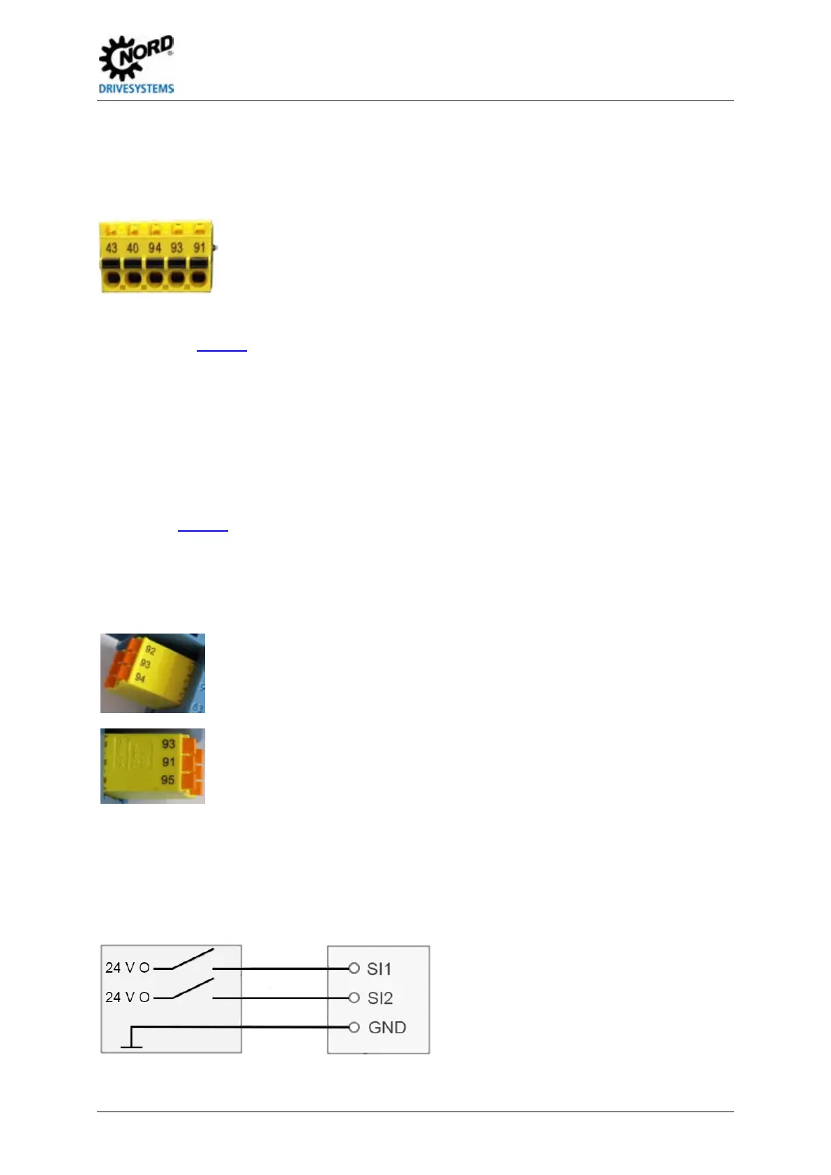
Safe Pulse Block Switch
The switch-off of the 24 V supply via contacts VIS1_24V_SH and VIS2_24V must be carried out by a
fail-safe switching device. As the interface SK CU5-STO is implemented as two channels with 2 x 24 V
IN (terminals 91 and 92) and as there is only one common ground, the Low side (GND) must not be
switched.
 Loading...


