P
Paige MooreAug 4, 2025
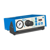
Why does the LED toggle between air and pressure and not accept the initiate signal on my Nordson EFD Controller?
- LLindsey AllenAug 4, 2025
If the LED on your Nordson EFD Controller toggles between air and pressure values and doesn't accept the initiate signal, it might be due to low air pressure. Ensure the input pressure is raised to 4.8 bar (70 psi). Then, press the Mode button to reset. If the issue continues, check for devices causing pressure drops in the ValveMate 7100 input air line.