EasyManua.ls Logo

Nordson EFD ValveMate 8040 - User Manual

Nordson EFD ValveMate 8040
26 pages
Print Icon
To Next Page IconTo Next Page
Loading...
ValveMate 8040 Controller
Operating Manual
Electronic pdf files of Nordson EFD
manuals are also available at
www.nordsonefd.com

Other manuals for Nordson EFD ValveMate 8040

Questions and Answers

Summary

Introduction

Nordson EFD Product Safety Statement

Electric Shock Hazard

Warning about electrical shock risk during operation or service.

Pressure and Burn Hazards

Warnings on maximum air pressure, releasing pressure, and hot surfaces.

Safety Hazards and Personnel

Halogenated Hydrocarbon Solvent Hazards

Hazards of using certain solvents with aluminum components.

High Pressure Fluid Dangers

Risks associated with high-pressure fluids and injection injuries.

Qualified Personnel Requirements

Need for trained personnel to operate and service the equipment.

Operational Safety and Regulations

Intended Use Guidelines

Defines proper and improper equipment usage.

Regulations and Approvals Compliance

Importance of adhering to regulations for approvals.

Personal Safety Precautions

General safety rules for operators and service personnel.

Fire Safety and Maintenance

Fire Safety Procedures

Precautions to prevent fire and explosion hazards.

Preventive Maintenance Schedule

Recommended checks for continuous trouble-free operation.

Component Safety and Malfunctions

Disposable Component Safety

Guidelines for safe handling and disposal of disposable parts.

Malfunction Response Steps

Procedures to follow in case of system malfunctions.

Equipment Disposal Guidance

Instructions for proper disposal of equipment and materials.

Specifications

Operating Features - Front Panel

Front Panel Buttons Overview

Explanation of each button's function on the front panel.

Operating Features - Indicators and Modes

Indicator Lamps Functionality

Description of the indicator lights and their meaning.

Modes of Operation Explained

Details on the different operational modes available.

Operating Features - Delay and Steady Mode

Delay Mode Operation Details

Explains the post nozzle air delay function.

Steady Mode Operation Setup

Instructions for setting up and using steady mode.

Typical Setup

Mounting and Power Supply

ValveMate 8040 Mounting Guide

Instructions for mounting the controller unit.

Input Power Supply Information

Details on the included 24VDC power supply.

Input;Output Connections

Initiate Connection - Alarm

Alarm IN;OUT Connection Setup

Procedures for connecting alarm input and output circuits.

Initiate Connection - Cycle and Output

End of Cycle (EOC) Feedback

Function of the EOC feedback signal for cycle completion.

24 VDC Courtesy Output

Details on the 24 VDC output for signaling or power.

Initiate Connection Schematic

Installing Solenoids and Valves

Air Solenoid Installation

Steps for mounting and connecting air solenoid packs.

Dispense Valve Installation

Guidance on setting up and connecting spray valves.

Final Setup Checklist

Testing the Spray Valves

Parts and Replacement Parts

Part Numbers List

List of available part numbers for the controller.

Replacement Parts Catalog

Catalog of parts available for replacement.

Troubleshooting

Nordson EFD One Year Limited Warranty

Overview

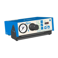
The ValveMate 8040 Controller is a reliable, high-quality dispensing system designed for industrial dispensing applications, offering years of trouble-free and productive service. It is an EFD spray valve controller that incorporates programmable dispense time, a digital time readout, four independent solenoid drivers, and input/output communication with host machine PLCs.

Function Description

The primary function of the ValveMate 8040 is to control the deposit size of fluids, which is achieved by adjusting the valve open time. This adjustment can be made easily and "on the fly" during operation. The controller manages up to four spray valves, allowing for independent or simultaneous control. It features a bright red LED display for clear time readout, ranging from 0.001 to 99.9 seconds, with a floating decimal for precise adjustments.

The system includes an ALARM I/O circuit that monitors air supply pressure and/or tank low level. If the alarm is activated, the display will flash "ALr," indicating a low pressure or tank level condition. This alarm can be connected to an audible alarm or to machine controls to shut off the machine. The ALARM IN circuit supports normally closed switches, such as low air pressure sensors or low-level fluid float switches. If no ALARM switch is used, a jumper must be installed across the ALARM IN positive (+) and negative (-) terminals to disable the feature. The ALARM OUT circuit is a normally OFF electronic switch that can activate an external signaling device or PLC input (5-24 VDC, 100 mA maximum).

An End Of Cycle (EOC) feedback signal is provided, which closes an open collector circuit upon completion of a spray cycle and remains closed until the next cycle. This signal can be used to communicate with a host computer, initiate other devices in a sequence, or confirm dispense cycle completion, thereby increasing machine productivity by eliminating unnecessary delays. The EOC circuit is open as long as an initiate sequence is in progress on any channel. The maximum load for the EOC output is 100 mA from 5 to 24 VDC. Additionally, a 24 VDC output (100 mA maximum) is available to power EOC and ALARM out circuits or to serve as a power source for an indicator device or initiate signal via a contact closure switch to the 4-channel Initiate circuit.

The ValveMate 8040 can be initiated through a time cycle by applying 5 to 24 VDC to the 1 INIT or 3 INIT input terminals. The 2 INIT and 4 INIT input terminals are not used for initiation. The four initiate inputs can be connected in series, parallel, or to separate input sources for independent valve control, or to disable a specific valve using "part in place" verification.

Usage Features

The ValveMate 8040 is designed for ease of setup and operation. Its front panel includes several buttons and indicator lamps to facilitate control:

  • SEL (Select) Button: Scrolls sequentially through the time settings for channels 1, 2, 3, and 4, depending on the selected MODE. The time in seconds is displayed on the LED.
  • MODE Button: Scrolls through the menu options (RUN, SETUP, PURGE, TEACH, DELAY) displayed to the left of the LED. It is also used for clearing ALARM faults.
  • RUN Mode: Enables external initiate inputs, disabling the CYCLE button. Time settings can be adjusted "on the fly" in this mode.
  • SETUP Mode: Allows for setup, testing, and modification of timer modes.
  • PURGE Mode: Enables individual or simultaneous purging of spray valves. This can occur with or without nozzle air function and is used to clear air from the fluid path.
  • TEACH Mode: Facilitates easy setting of times for longer spray cycle applications. In TEACH mode, pressing and holding the CYCLE button initiates a 5-second "flashing" of the LED display, after which incremental time can be added by continued pressing of the CYCLE button.
  • DELAY Mode: Allows users to increase or decrease the post-nozzle air delay after spray valve actuation, ensuring all fluid is atomized for a clean nozzle.
  • CYCLE Button: Provides different results depending on the selected MODE. In RUN mode, it locks in new time settings after "on the fly" adjustments. In PURGE mode, it actuates the spray valves for purging. In TEACH mode, it initiates the teaching sequence.
  • UP/DOWN Buttons: Used to change the valve-on time for selected valves or the DELAY time. Pressing both buttons simultaneously zeros out the time. These buttons are active in RUN, SETUP, and DELAY modes.
  • Steady Mode Operation: Channels can be set to a steady mode/time override. In SETUP mode, pressing SEL for a selected channel and then pressing both UP/DOWN buttons simultaneously to ".000" will clear the channel time. Holding the DOWN button for 5 seconds until "- - -" appears on the LED display sets the channel to steady mode. To return to time setting, re-enter SETUP mode, select the channel, and press UP/DOWN buttons simultaneously to display ".000," then re-enter the desired time.

The ValveMate 8040 is designed to be mounted either over or under a cabinet using screws or panel-mounted with an optional bezel mount. A universal 24VDC remote power supply is included, requiring connection to an appropriate input voltage.

Maintenance Features

Nordson EFD recommends simple preventive maintenance checks to ensure continuous trouble-free use:

  • Periodic Inspection: Regularly inspect tube-to-fitting connections for proper fit and secure them as necessary.
  • Tubing Check: Check tubing for cracks and contamination, replacing it as needed.
  • Wiring Connections: Verify all wiring connections for looseness and tighten them as necessary.
  • Cleaning: For front panel cleaning, use a clean, soft, damp rag with a mild detergent cleaner. Avoid strong solvents (MEK, acetone, THF, etc.) as they can damage the front panel material.
  • Air Supply: Maintain a clean, dry air supply to the unit. The equipment does not require any other regular maintenance.
  • Testing: Verify the operation of features and equipment performance using the appropriate sections of the manual. Faulty or defective units should be returned to Nordson EFD for replacement.
  • Replacement Parts: Use only replacement parts designed for the original equipment. Contact your Nordson EFD representative for information and advice.

In the event of a malfunction, the system should be shut off immediately. Steps include disconnecting electrical power, closing hydraulic and pneumatic shutoff valves, relieving pressure, removing syringe barrels (for air-powered dispensers), identifying the cause of the malfunction, and correcting it before restarting.

The ValveMate 8040 is not equipped with an ON/OFF switch; it remains in an ON condition as long as input power supply voltage is maintained.

Nordson EFD ValveMate 8040 Specifications

General IconGeneral
Control TypeDigital
Output Voltage24 VDC
Number of Channels4
Number of ValvesUp to 4
Valve ControlSolenoid
Pressure Resolution1 psi (0.07 bar)
Communication InterfaceRS-232
Weight1.5 kg (3.3 lb)
Input Voltage100-240 VAC
Operating Temperature10-40 °C (50-104 °F)
Pressure Range0 to 100 psi (0 to 6.9 bar)
Power Supply24 VDC
Dispense Time Adjustment0.001-99.999 seconds

Related product manuals