
B
Barbara SilvaAug 3, 2025
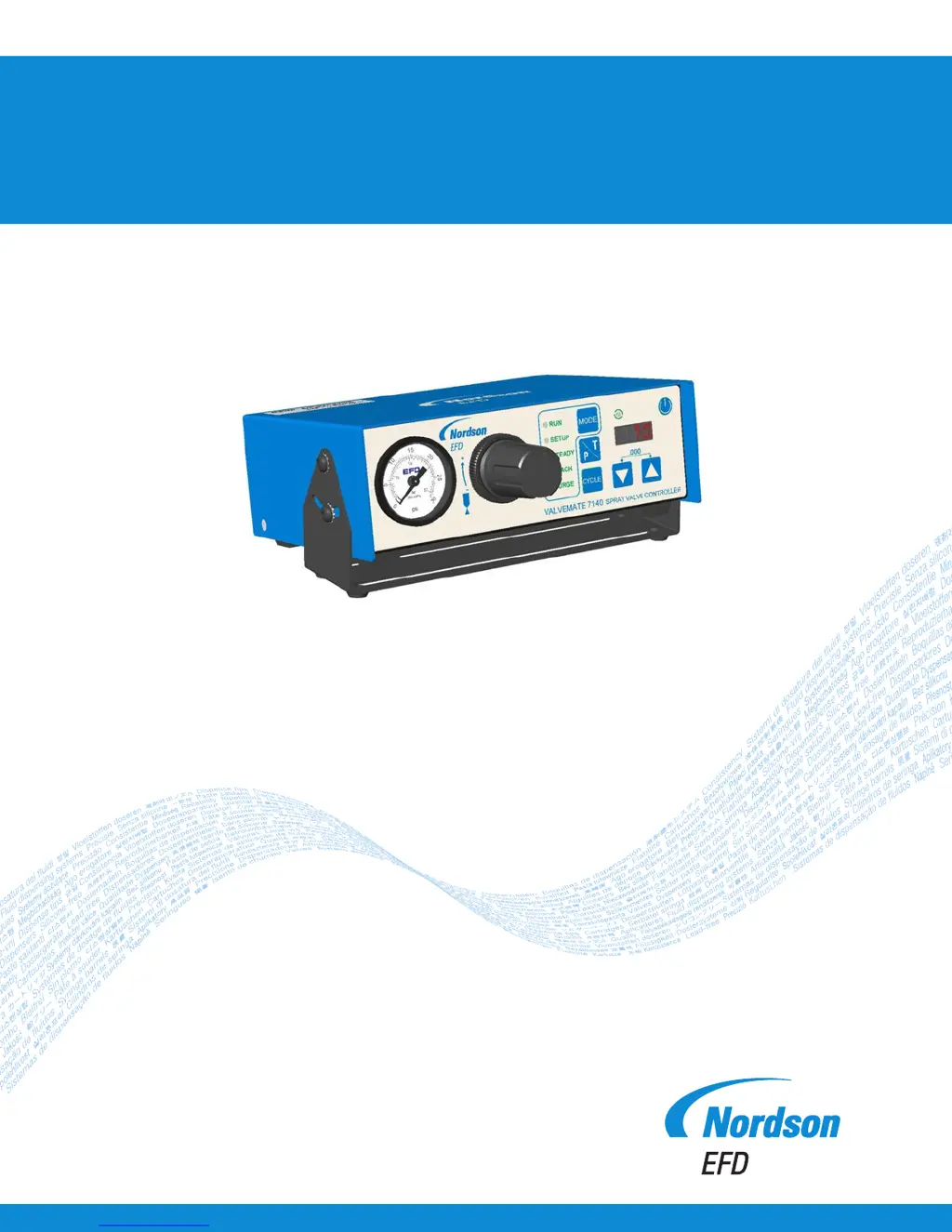
What to do if Nordson EFD ValveMate 7140 is not responding to the initiate signal?
- MmatthewjohnsonAug 3, 2025
First, ensure the Nordson EFD Controller is in RUN mode. If it is, consider that if the dispense time is set at or below 0.010 seconds, the pneumatic circuit's response delay might prevent the valve from opening. Try increasing the dispense time. Also, ensure that the signal breaks cleanly before initiating the next signal.


