J
jose77Aug 17, 2025
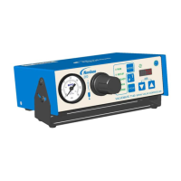
Why is my Nordson EFD PICO Touch leaking fluid?
- MmistysandersAug 17, 2025
Fluid leaks can occur for several reasons. First, check that the valve power is turned on. If it is on, the issue may be due to insufficient closing voltage, in which case you should increase the valve's closing voltage. Another cause could be an improperly selected profile; if RAMP isn't selected for the open and close WAVE PROFILE settings, verify the selected profile is correctly programmed. The valve itself may be worn or damaged, or the driver may be damaged. In these cases, you should refer to the valve operating manual or contact Nordson EFD.