PICO Toµch Controller
34 www.nordsonefd.com info@nordsonefd.com 800-556-3484 Sales and service of Nordson EFD dispensing systems are available worldwide.
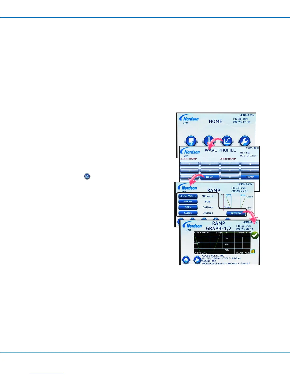
Adjusting the Wave Profile
The WAVE PROFILE screen includes valve close and valve open prole
selections for optimizing or ne-tuning your dispensing results. The
Close proles affect how fast the valve closes. The Open proles affect
how fast the valve opens. You can also choose RAMP, which allows the
system to create Open and Close proles based on the values entered
on the RAMP screen.
NOTE: Buttons are available for custom wave proles. Contact your
Nordson EFD representative for information on creating custom wave
proles and for using the pre-programmed wave prole selections.
1. Press the RAMP icon ( ).
2. Select the desired wave prole for Close (how fast the valve closes)
and / or Open (how fast the valve opens), or
Press RAMP to open the RAMP screen. On the RAMP screen, enter
the values you want the system to use to create Close and Open
proles.
• CLOSE VOLTS: The voltage applied to close the valve. The
higher the voltage, the greater the sealing force
applied.
• STROKE: The voltage applied for each initiate cycle. For
example, a CLOSE VOLTS setting of 120V and
a STROKE setting of 50% means that when
the valve actuates, the voltage changes from
120V to 60V and then back to 120V, as shown
by the wave prole PREVIEW.
• OPEN: How fast the valve opens.
• CLOSE: How fast the valve closes.
• PREVIEW: Opens the RAMP GRAPH screen, which
displays a graph of the CLOSE: > RAMP and
OPEN: > RAMP wave prole (this screen does
not provide a graph for any custom proles).
NOTE: Minimum limits are valve-specic and will be updated by
the controller if they are exceeded.
3. Press HOME to save the setting and return to the HOME screen.
Setup and Programming Procedures (continued)
Connecting a Controller Status Monitoring Signal
The Pµlse valve is normally open and power must be applied to close it. In the case of damage to the piezo actuator
or the Toµch controller, the valve may transition from a CLOSED to an OPEN condition, which can cause uid
release. Nordson EFD recommends continually monitoring the status signal of the Toµch controller and immediately
and automatically de-pressurizing the system if the signal indicates an error. Follow this procedure to connect a
controller status monitoring signal.
Connect wiring from the monitoring device to the following pins of the I/O port on the back of the controller:
• Pin 7 — Power signal
• Pin 13 — Error Out signal
Refer to "Input / Output Port Pin Descriptions" on page 46 for detailed I/O information.

 Loading...