S 24 VDC power supply cable (see a Figure 3)
S ground wires (see c Figure 3)
S Ethernet cable (see b Figure3).Makesureto
cut wire ties that hold the Ethernet cable.
4. Unfasten the two captive screws that hold the touch screen
panel to the base panel (see d in Figure 2).
Figure 3
Removing the Controller Board, contd.
c
a
d
c
Figure 4
a: Power supply board b: Four screws c: Hexagonal stands d: Plastic standoffs
e: Six terminal blocks f: JP 7 on the controller board g: Touch screen 24 VDC supply
h: Line voltage board i: Ground wire
power supply
b
5. Remove the touch screen panel (see a in Figure 2) by
compressing the standoffs (see b in Figure 2).
6. Disconnect the following cables (see Figure 3):
7. Disconnect the following:
b
e
f
g
a
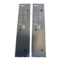
8. Unfasten the four screws (see b in Figure 4) to remove
the old power s upply board (see a in Figure 4).
9. Remove the four hexagonal stands (see c in Figure 4).
h
i
j
a: 24 VDC s upply cable b: Ethernet cable
c: Ground wires
S 24 VDC supply cable from JP7 on the controller board
(see f in Figure 4).
S main line voltage supply from the board (see j in Figure 4)
S board line voltage supply from the board (see h in Figure 4)
S power supply ground wire
10. Remove the four plastic standoffs (see d in Figure 4).
11. Remove the six remaining terminal block connectors
from the controller board (see e in Figure 4).
12. Unfasten the seven mounting screws from the con-
troller board and remove. See Figure 1 in Installing the Con-
troller Board.

 Loading...