23
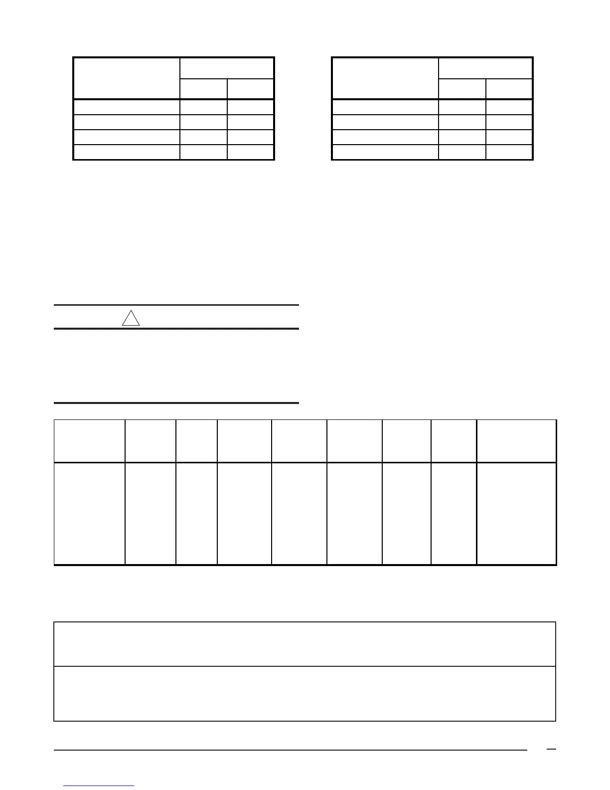
Table 8. Natural and LP Gas Orifice Sizes for Elevations
between zero and 4999 ft. Above Sea Level
Table 9. Natural and LP gas Orifice Sizes for Elevations
between 5000 and 10,000 ft. Above Sea Level
Note: (†) can be C or N.
* Time-delay fuses or HACR-type circuit breakers are required.
Table 10. Electrical Data
Thermostat Wire Gauge Recommended Thermostat Wire Length
2-wire 4 or 5-wire
(heating) (cooling)
24 55 ft. 25 ft.
22 90 ft. 45 ft.
20 140 ft. 70 ft.
18 225 ft. 110 ft.
Furnace Rating Furnace Rating
Plate Input (Btu/h)
Nat LP
Plate Input (Btu/h)
Nat LP
72000 43 54 72000 43 55
96000 43 54 96000 43 55
120000 43 54 120000 43 55
144000 43 54 144000 43 55
Orifice Drill Size Orifice Drill Size
Line Voltage Wiring
The line voltage (115 volt) to the furnace must be supplied
from a dedicated branch circuit containing the correct fuse or
circuit breaker for the furnace. (See Table 10.) An electrical
disconnect must be installed to be readily accessible from
and located within sight of the furnace. (See the Wiring
Diagram label in the furnace and Figure 22.)
!
CAUTION:
Label all wires prior to disconnection when
servicing controls. Wiring errors can cause
improper and dangerous operation.
Verify proper operation after servicing.
The furnace cabinet must have an uninterrupted, unbroken
ground to minimize injury should an electrical fault condition
occur. The controls used in this furnace require an
earth ground to operate properly. Acceptable methods
for grounding are electrical wire or conduit approved for
electrical ground service. Do not use gas piping as an
electrical ground.
IMPORTANT NOTE:
Proper line voltage polarity must be maintained in
order for the control system to operate correctly. Verify
that the incoming neutral line is connected to the white
wire and the incoming “hot” line is connected to the
black wire. These furnaces will not operate unless the
polarity and ground are properly connected. See Figure
22.
Furnace Furnace Cabinet Nominal Maximum Minimum Maximum Minimum Maximum
Model Number Input Width Electrical Operating Operating Furnace Wire Fuse or Circuit
*RA/*RK (Btu/hr) (in.) Supply Voltage Voltage Amperes Gauge Breaker Amps*
072(†)-16 72,000 19.75 115-60-1 127 103 9.0 14 15
096(†)-12 96,000 19.75 115-60-1 127 103 7.1 14 15
096(†)-16 96,000 19.75 115-60-1 127 103 9.0 14 15
096(†)-20 96,000 22.50 115-60-1 127 103 12.2 12 20
120(†)-16 120,000 19.75 115-60-1 127 103 9.0 14 15
120(†)-20 120,000 22.50 115-60-1 127 103 12.2 12 20
144(†)-20 144,000 22.50 115-60-1 127 103 12.2 12 20
 Loading...