6
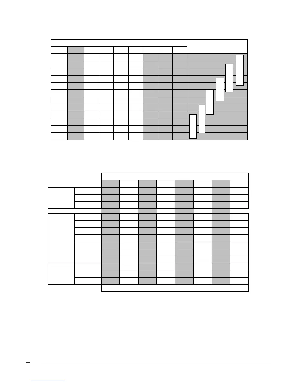
CAPACITIES —Furnace Airflow Data
720 900 1056 1200 1350 1500 1656 1800
7
1
0
1
0
1
0
1
0
6
0
0
0
0
1
1
1
1
5
0
0
1
1
0
0
1
1
72,000 59
51
44
90,000 63
55
49 44
96,000 67 59
53
47
108,000 67
59
53 48
120,000 66
59
54 49
126,000 69 62
56
51
144,000 71
64
59
80,000 67
59
52 47
100,000 73 65
59
53 49
120,000 71
64
59
Temperature Rise °F (Recommended settings are
Bold
)
Nominal Air-Flo
80+% 92+%
Switches
Table 2. Heating Airflow Settings
NOTE: 0 = OFF 1 = ON
Nominal A/C and HP
LOW HIGH 1 2 3 4
567
Capacity
500 720 0 0 0 1
550 800 0 0 0 0
610 880 0 0 1 0
650 945 1 0 0 1
72010501000
80011551010
90013050101
1000 1450 0 1 0 0
1060 1530 1 1 0 1
1100 1595 0 1 1 0
1170 1700 1 1 0 0
1290 1870 1 1 1 0
CFM SWITCH NUMBER
2 TON
3.5 TON
4 TON
5 TON
3 TON
2.5 TON
Table 1. Cooling/Heat Pump Airflow Settings
NOTE: 0 = OFF 1 = ON
Notes:
1. Recommended temperature rises are highlighted in bold.
2. Airflow rates of 1800 CFM or more require two return air connections. Data is for operation with filter(s).
3. Temperature rises in the table are approximate. Actual temperature rises may vary.
4. Temperature rises that are shaded grey are for reference only. These conditions are not recommended.
5. For single stage cooling, the indoor blower will operate at the CFM listed in the high column.
 Loading...