26
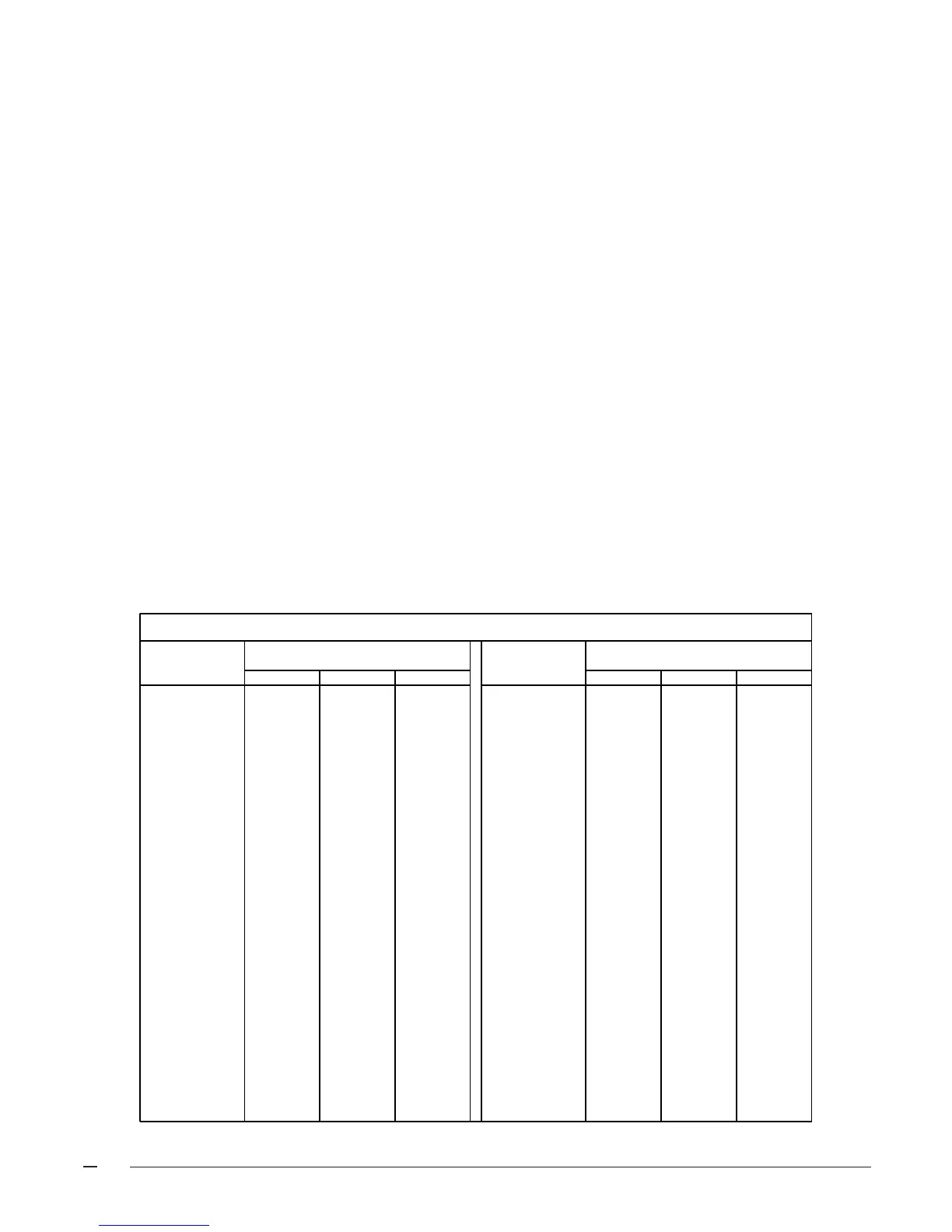
Table 11. Gas Flow Rate
TIME FOR TIME FOR
ONE REVOLUTION ONE REVOLUTION
(SECONDS) 1 5 10 (SECONDS) 1 5 10
10 360 1800 3600 66 55 273 545
12 300 1500 3000 68 53 265 529
14 257 1286 2571 70 51 257 514
16 225 1125 2250 72 50 250 500
18 200 1000 2000 74 49 243 486
20 180 900 1800 76 47 237 474
22 164 818 1636 78 46 231 462
24 150 750 1500 80 45 225 450
26 138 692 1385 82 44 220 439
28 129 643 1286 84 43 214 429
30 120 600 1200 86 42 209 419
32 113 563 1125 88 41 205 409
34 106 529 1059 90 40 200 400
36 100 500 1000 92 39 196 391
38 95 474 947 94 38 191 383
40 90 450 900 96 38 188 375
42 86 429 857 98 37 184 367
44 82 409 818 100 36 180 360
46 78 391 783 102 35 176 353
48 75 375 750 104 35 173 346
50 72 360 720 106 34 170 340
52 69 346 692 108 33 167 333
54 67 333 667 110 33 164 327
56 64 321 643 112 32 161 321
58 62 310 621 114 32 158 316
60 60 300 600 116 31 155 310
62 58 290 581 118 31 153 305
64 56 281 563 120 30 150 300
GAS FLOW RATE (CUBIC FEET PER HOUR)
CUBIC FEET PER REVOLUTION OF
METER
CUBIC FEET PER REVOLUTION OF
METER
Selecting The Cooling/Heat Pump Airflow
In order to select the appropriate airflow for AC and HP
operation the nominal system capacity must be known.
The nominal system capacity is ALWAYS the nominal
capacity of the outdoor unit. In some cases the nominal
system capacity is not the same as the nominal capacity
of the indoor coil.
The cooling/heat pump airflow is selected by setting
switches 1 through 4 on the motor control board located in
the blower control panel. All airflows for other modes of
operation (except gas heat) are determined by this setting.
Table 1 shows the airflow values versus the airflow selector
switch settings, and the range of airflow settings recom-
mended for each nominal system capacity.
NOTE: The CFM values listed on Table 2 are not
dependent on duct static pressure. The motor auto-
matically compensates for changes in duct static pres-
sure (within the limits of the motor).
For Two Stage Cooling:
The furnace is supplied with the yellow "Y1" and blue "Y2"
connections attached to the control board. When installing
this furnace with a two stage condensing unit, remove the
blue "Y2" wire from the control board and connect to the
thermostat. Connect a field supplied wire from the yellow
"Y1" to the thermostat and the condensing unit, and
another wire from "Y2" on the thermostat to "Y2" on the
condenser. (See Figure 23).
For maximum capacity and energy efficiency, generally, a
selection at or near the top of the CFM range for that
nominal capacity is best. For maximum dehumidification,
select an airflow near the middle or bottom of the CFM
range for that nominal capacity.
IMPORTANT NOTE: When installing a 2-stage heat
pump with a fossil fuel kit, the transformer in the
furnace MUST be upgraded to one with a 60VA rating
(Part No. 904077).
NOTE: If coil icing is observed, the cooling/heat pump
airflow selected may be too low. Double-check to be
sure the setting selected is within the range shown in
Table 1. Also check to be sure the system is properly
charged (see outdoor unit installation instructions). If
icing continues to occur, raise the selected airflow one
or two steps.
Verifying and Adjusting Temperature Rise
Verify the temperature rise through the furnace is within the
range specified on the furnace rating plate. Temperature
 Loading...