3
The plenum connectors are designed for
use with trunk ducts having a minimum
width of 12 in. If sufficient space is not
available to adequately bend and secure
plenum tabs it may be necessary to attach
the connector to the duct using sheet-
metal fasteners and seal with an approved
foil tape.
Plenum connectors may be field con-
structed but must meet requirements as
stated in the unit installation instructions.
Table 1. Optional Accessory Kits
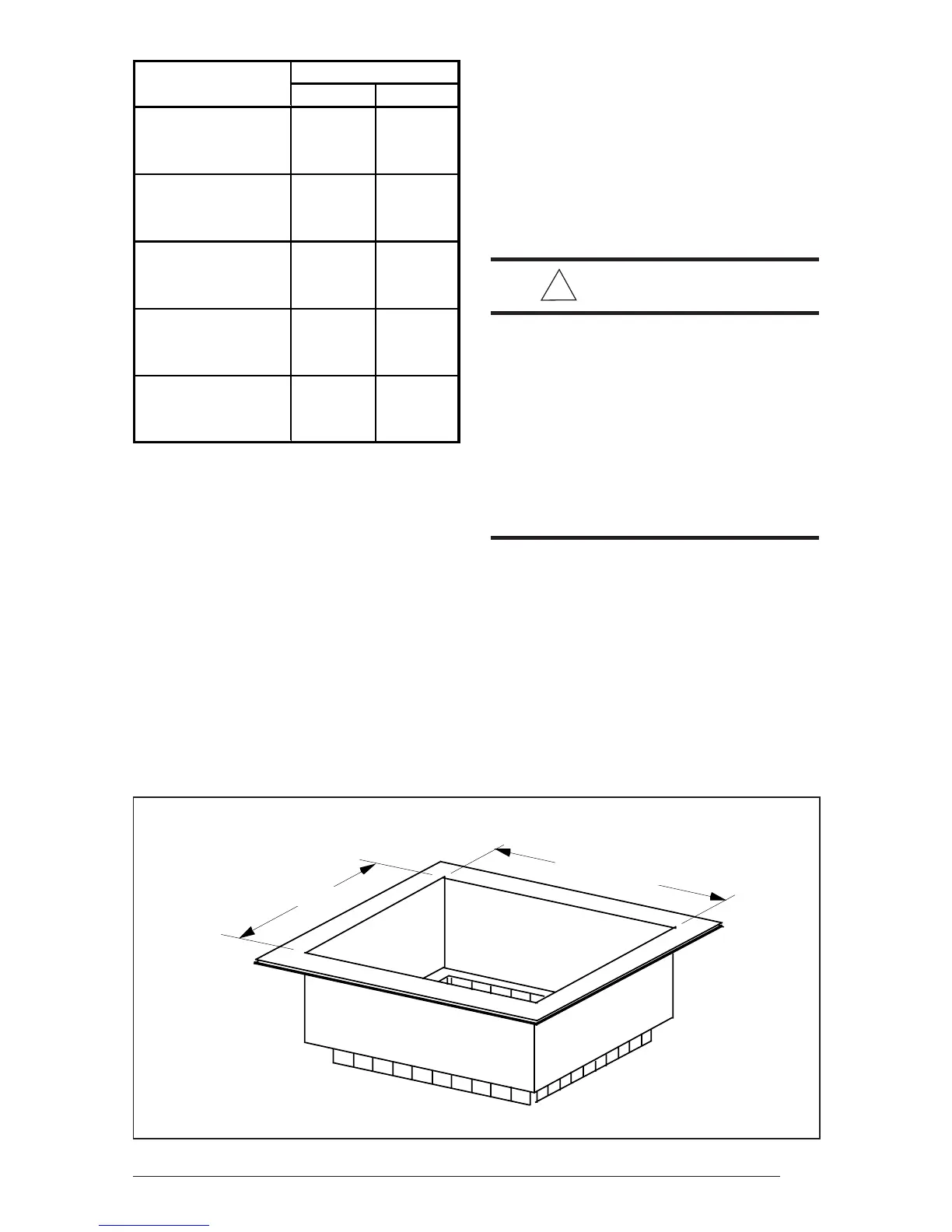
Figure 1. Plenum Adapter
13.25"
18.5" (B-Cab.)
21.25" (C-Cab.)
INSTALLATION
Install the unit as directed in the Installa-
tion Instructions. NOTE: Secure the unit to
the structure using metal strap and/or fas-
teners at the top of the unit and at the
bottom of the unit.
POWER WIRING
!
WARNING:
To avoid risk of electric
shock, personal injury, or
death, disconnect electrical
power to the unit before
performing any maintenance
or service. The unit may have
more than one electric power
supply.
All wiring must comply with the current
revision of the National Electric Code and
must be sized for the minimum ampacities
as listed on the unit data label or in Table
2.
If a single circuit adaptor kit is used, it may
need to be re-configured for some appli-
BC
913840 914969
913841 914970
913842 914971
913872 913873
917343A 917344A
Cabinet Size
Description
Downflow Plenum
Connector, 6.25"
Downflow Plenum
Connector, 8.25"
Downflow Plenum
Connector, 10.25"
Upflow Pedestal
Mounting Stand
Downflow Coil
Adaptor

 Loading...