9
• Connect the line-voltage leads to the
terminals on the contactor inside the control
compartment.
• Use only copper wire for the line voltage power
supply to this unit (Table 1). Use proper code
agency listed conduit and a conduit connector
for connecting the supply wires to the unit.
Use of rain tight conduit is recommended.
• See the unit wiring label for proper high and low
voltage wiring. Make all electrical connections
in accordance with all applicable codes and
ordinances.
• Use a separate branch electrical circuit for this
unit. A means of electrical disconnect must be
located within sight of and readily accessible
to the unit. This switch shall be capable of
electrically de-energizing the outdoor unit.
• Overcurrent protection must be provided at the
branch circuit distribution panel and sized as
shown on the unit rating label and according
to applicable local codes.
Outdoor Unit Connections
The outdoor unit requires both power and control
circuit electrical connections. Refer to the unit
wiring diagram / schematic for identifi cation and
location of outdoor unit fi eld wiring interfaces.
Control Circuit Wiring
The outdoor unit is designed to operate from a
24 VAC Class II control circuit. The control circuit
wiring must comply with the current provisions
of the NEC (ANSI/NFPA 70) and with applicable
local codes having jurisdiction.
Thermostat Connections
Thermostat connections should be made in
accordance with the instructions supplied with
the thermostat, and with the instructions supplied
with the indoor equipment. See Table 2 for proper
wire gauge and their recommended lengths
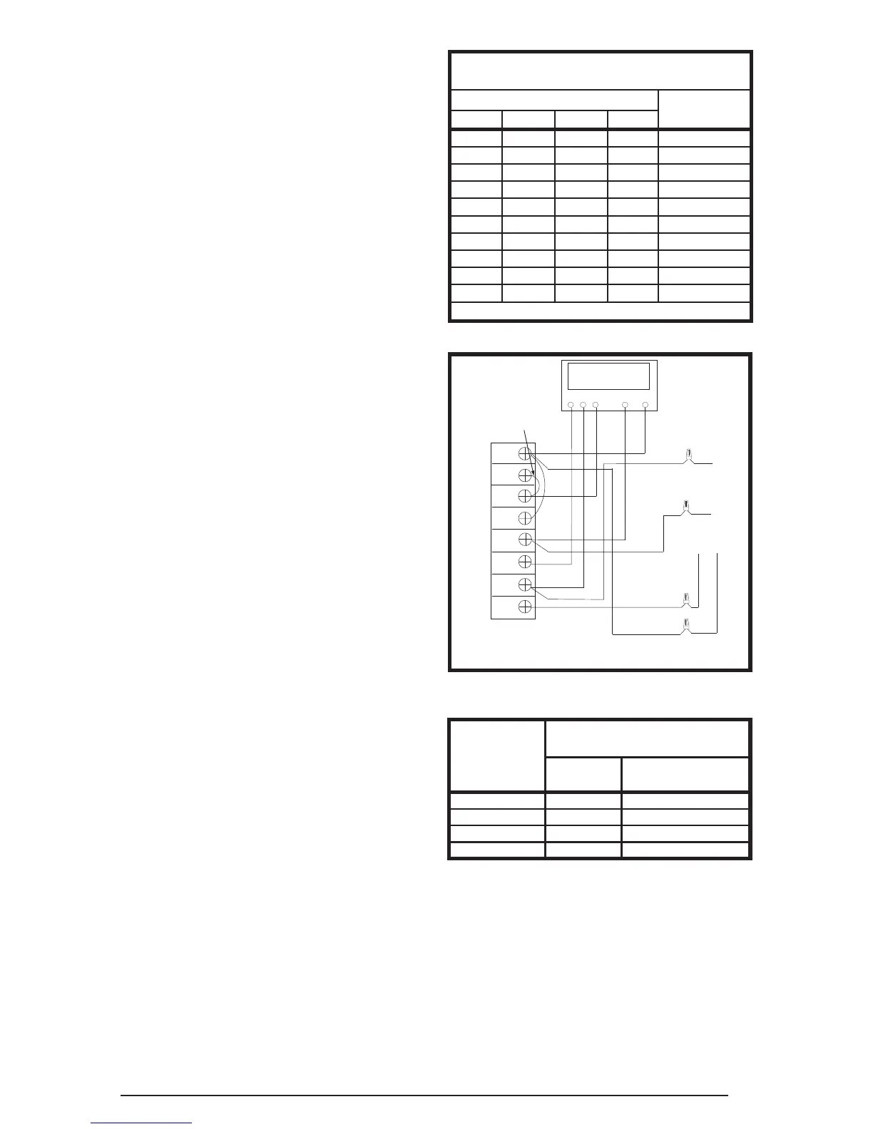
for typical thermostat connections. A typical
residential installation with an air conditioner,
thermostat, and air handler is shown in Figure 2.
Figure 2. Typical 2-Stage Air Conditioner
with Variable Speed Air Handler
GRW
Thermostat
Y1C
Air Handler
A/C OD Section
Y1
W2
W1
O
Y/Y2
G
R
C
Y2
Y2
R
Y1
NOTE: Jumper
W1 and W2
together for
shorter staging
time. See Table 2
NOTE: in AC applications,
the O & Y connection must
be connected as shown.
Low-Pressure Switch
A low-pressure switch is factory installed and
located internally on the suction line of the
outdoor unit. The switch is designed to protect the
compressor from a loss of charge by interrupting
the thermostat inputs to the unit.
If the suction pressure falls below 5 psig, the
switch will open and de-energize the outdoor
unit. The switch will close again when the suction
pressure increases above 20 psig. NOTE: When
the switch opens and then closes, there is a 5
minute short cycling delay before the outdoor
unit will energize. Under normal conditions the
switch is closed.
Table 2. Thermostat Wire Gauge
Thermostat
Wire Gauge
Recommended T’STAT Wire
Length (Unit to T’STAT)
2-Wire
(Heating)
5-Wire
(Heating/Cooling)
24 55 25
22 90 45
20 140 70
18 225 110
COPPER WIRE SIZE — AWG
(1% Voltage Drop)
Supply Wire Length-Feet
Supply Circuit
Ampacity
200 150 100 50
6 8 10 14 15
46812 20
46810 25
44610 30
3468 35
3468 40
2346 45
2346 50
2346 55
1234 60
Wire Size based on N.E.C. for 60° type copper conductors.
Table 1. Copper Wire Size
High-Pressure Switch
A high-pressure switch is factory installed and
located internally on the compressor discharge
line of the outdoor unit. If the discharge pressure
rises above 650 psig, the switch will open and
de-energize the outdoor unit. The switch will close
again after the discharge pressure decreases to
460 psig. NOTE: When the switch opens and
then closes, there will be a 3 minute short cycling
delay before the outdoor unit will energize. Under
normal conditions the switch is closed.
 Loading...