11
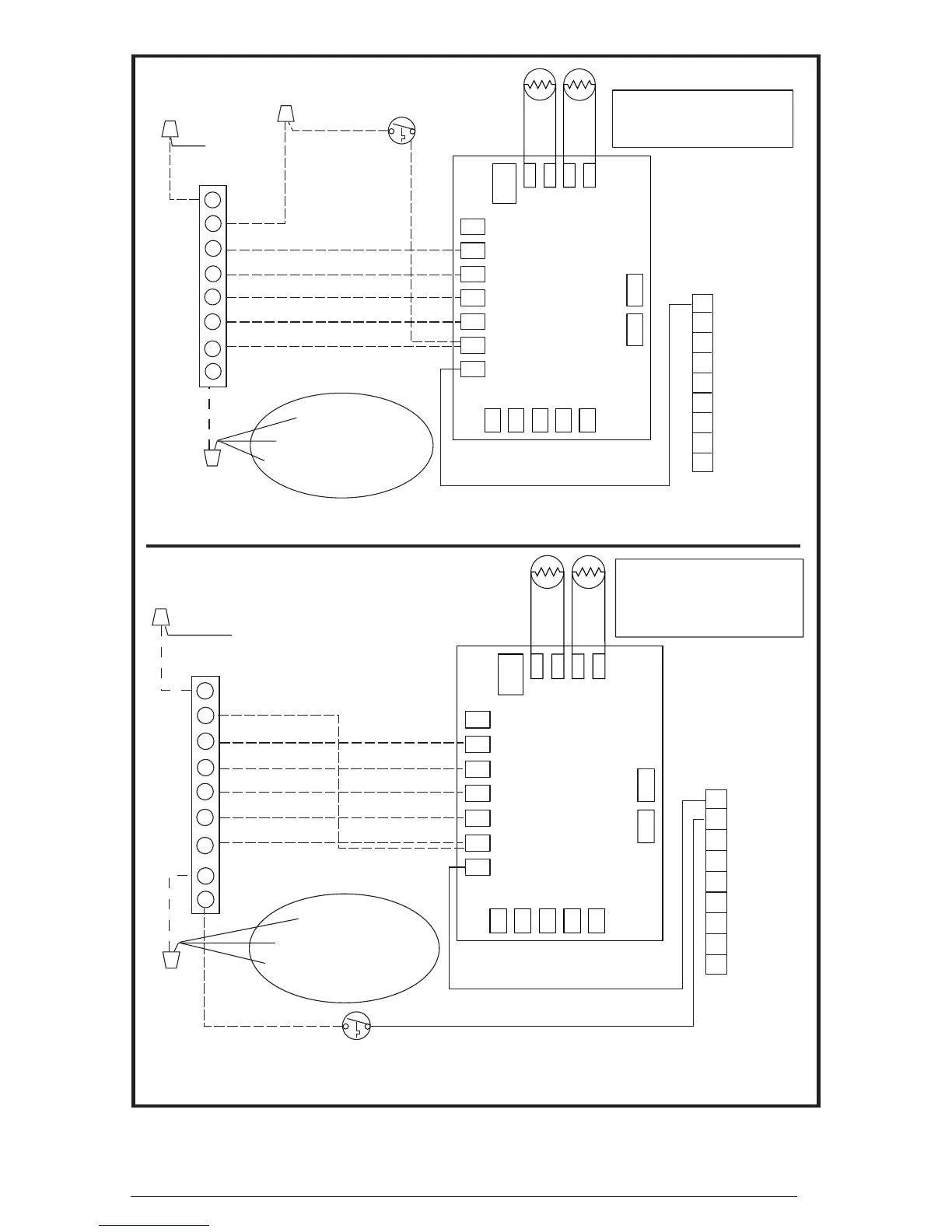
Figure 10. Typical Heat Pump Thermostat Connections
Typical Wiring (Field Supplied) for 2-Stage Cool, 2-Stage Electric Heat
Typical Wiring (Field Supplied) for 2-Stage Cool, 1 Stage Electric Heat
E
O
G
R
Y1
INDOOR THERMOSTAT
SUB-BASE
Y2
W1
C
1
2
3
4
5
6
7
8
9
Brown
Orange
Accessory
Heat Plug
AMBIENT
SENSOR
COIL
SENSOR
TEST
LRCYO
W2
IN
W2
OUT
COND FAN
AMBIENT
AMBG
COILG
COIL
DEMAND
DEFROST CONTROL
BOARD
M
PRESS
SW
REV
VALVE
Demand Defrost Board
Outdoor Thermostat
(optional)
Blower Relay
Compressor Solenoid
ECM Motor (if applicable)
Y1 = 1st Stage Heat Pump
Y2 = 2nd Stage Heat Pump
W1 = 1st Stage Auxillary Heat
Green
(from blower relay)
1
2
3
4
5
6
7
8
9
Brown
Orange
Accessory
Heat Plug
AMBIENT
SENSOR
COIL
SENSOR
TEST
LRCYO
W2
IN
W2
OUT
COND FAN
AMBIENT
AMBG
COILG
COIL
DEMAND
DEFROST CONTROL
BOARD
M
PRESS
SW
REV
VALVE
Demand Defrost Board
Outdoor Thermostat (optional)
Y1 = 1st Stage Heat Pump
Y2 = 2nd Stage Heat Pump
W1 = 1st Stage Auxillary Heat
W2 = 2nd Stage Auxillary Heat
E
O
G
R
Y1
INDOOR THERMOSTAT
SUB-BASE
Y2
W1
C
W2
Blower Relay
Compressor Solenoid
ECM Motor (if applicable)
Green
(from blower relay)
 Loading...