12
8.
Vent Pipe Installation
(Indoor Installation Only)
WARNING
Be sure to do
CARBON MONOXIDE POISONING
Follow all vent system requirements in accordance
with relevant local or state regulation, or, in the
absence of local or state code, in the U.S. to the
National Fuel Gas Code ANSI Z233.1/NFPA 54 –
latest edition, and in Canada, in accordance with the Natural
Gas and Propane Installation Code CSA B149.1 – latest edition.
No. of Elbows
Max. Straight Vent Length*
4 39' (11.7m) N/A
3 45' (13.5m) 15' (4.5m)
2 51' (15.3m) 30' (9.0m)
1 57' (17.1m) 45' (13.5m)
Pipe diameter 4" (100mm) 5" (127mm)
•
This appliance has been designed to be vented
with 4" (100mm) PVC, CPVC or PP pipe.
•
This appliance has been designed to be vented
with 5" (127mm) N-Vent or Category III vent by
using 4" PVC to 5" SS Vent Adapter.
Do not exceed the following maximum vent lengths:
• The venting system shall be installed in
accordance with the water heater manufacturer's
instructions and, if applicable, the venting
system manufacturer's instructions.
• This is a Category IV appliance.
Only vent materials approved for use with
Category IV appliances should be used.
• Under normal conditions, this appliance will not
produce an exhaust ue temperature in excess
of 149°F (65°C) and schedule 40 PVC pipe may
be used as the vent material.
If the water heater
set temperature is 160°F (70°C) or higher and
there is a return line to the water heater from
either a recirculation pump or a combination
space heating system, schedule 40/80 CPVC
or PP must be used.
Refer to page 14 for additional requirements.
•
Make sure the vent system is gas tight and will not leak.
• Support the vent pipe with hangers at regular
intervals as specied by these instructions or
the instructions of the vent manufacturer.
•
All piping must be fully supported. Use pipe hangers
at a minimum of 3 ft (0.9 m) intervals. Do not use
the Water Heater to support the vent piping.
• Do not common vent or connect more than one
appliance to this venting system.
•
The total vent length including horizontal &
vertical vent runs should be no less than 3' (0.9m).
•
Steam or condensed water may come out from the
vent termination. Select the location for the termination
so as to prevent injury or property damage.
• If snow is expected to accumulate, take care the
end of the pipe is not covered with snow or hit
by falling lumps of snow.
• The vent for this appliance shall not terminate:
i) over public walkways; or
ii) near sot vents or crawl space vents or
other areas where condensate or vapor could
create a nuisance or hazard or cause property
damage; or
iii) where condensate vaper could cause
damage or could be detrimental to the
operation of regulators, relief valves, or other
equipment.
General Requirements Maximum Vent Lengths
* Not including the termination
Refer to page 17 for max. vent lengths
when using PVC Concentric Termination.
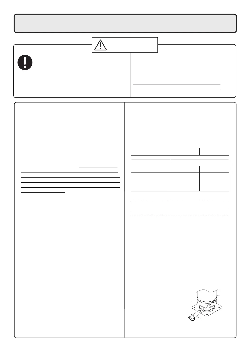
1. Continue to insert the Vent Pipe until it
reaches to the base of the unit Exhaust and
Intake Flue. (The Vent Pipe will be inserted
approximately 1.6"(40mm).)
2. Secure the Vent
Pipe by tightening
the band using a
screwdriver. (The
tightening torque
shall be more than
16 in lb.)
How to tighten the Vent Pipe
Exhaust and
Intake Flue
Vent Pipe
Screwdriver
-Flat head
-Box wrench(5/16")
Clearances
PVC, CPVC or PP has been approved for use on
this appliance with zero clearance to combustibles.
• The exhaust and intake pipes must be the
same vent pipe diameter.
Venting with PP pipe
• Do not deform the PP pipe when cutting.
• Deburr the cut end so that damage to the
gasket is avoided.
•
Remove debris from inside the pipe prior to assembly.
Damaged gaskets can cause leakage of
dangerous levels of carbon monoxide or
property damage due to condensate leaks.
 Loading...