Procedure Diagram
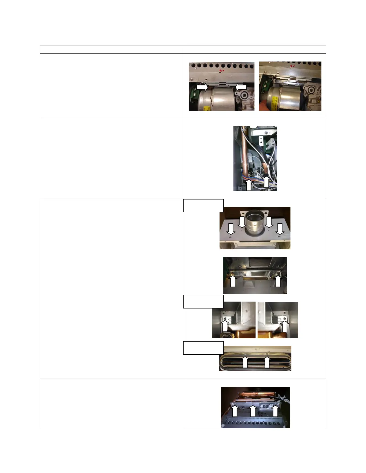
5. Remove fan
(1) Remove the 2 screw on both sides of
the fan, screws are located on back
side of the case
(2) When the screws are remove the back
side of the fan with drop down and fan
will rotate out
6.
Disconnect water pipes coming from the
heat exchanger.
(1) Remove both “C” clamps for the inlet
and outlet pipes from the heat
exchanger
7. Remove heat exchanger from case
(1) Remove the 4 case top cover screws
(This step will be skipped with OD
Model Units)
(2) Remove the 2 set screws on the
bottom of the burner
(3) Remove the upper left and right set
screws near the top of the case (OD
Models the screws will be at the top
center of the case)
(support bottom of assembly)
8.
Separate burner from heat exchanger
Remove 10 screws holding burner to
heat exchanger
OD Models
SV Models
SV Models
 Loading...