35
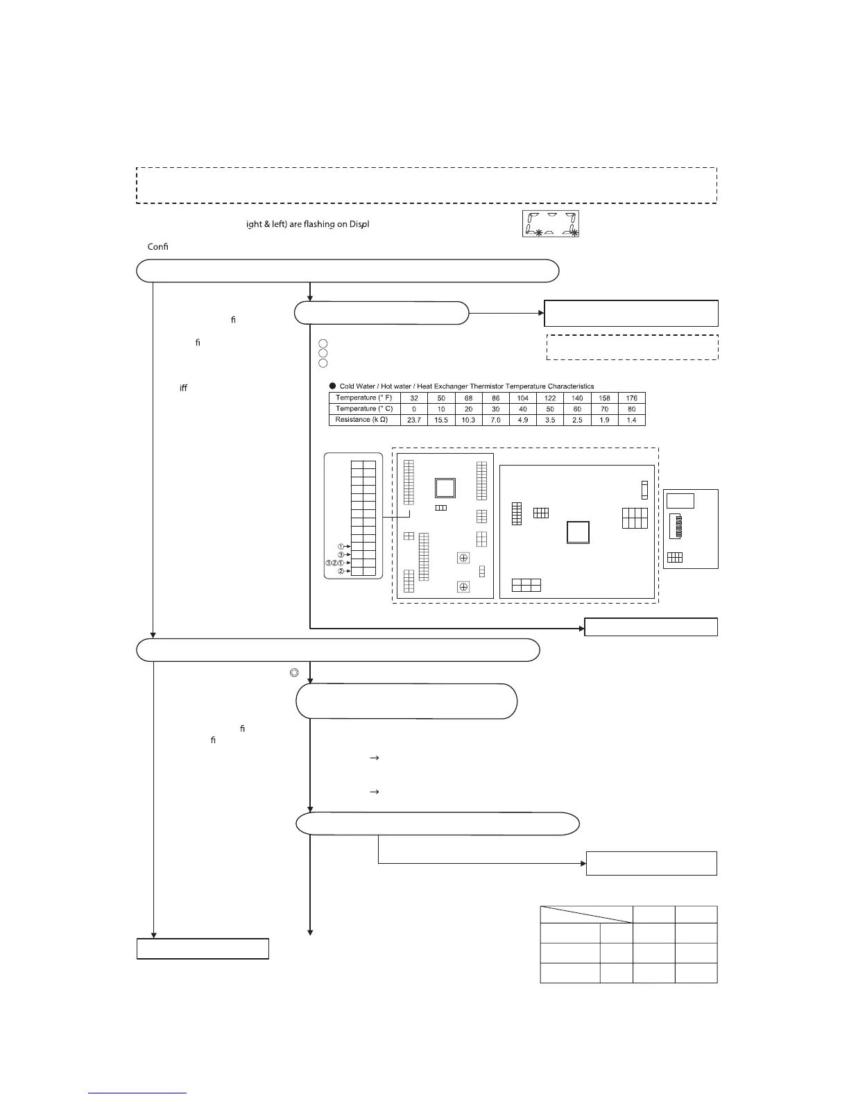
1-3. Outlet water temperature incorrect
No abnormality in appliance.
B
Check whether the Thermistor-Cold Water / Hot Water / Heat Exchanger are normal.
Check that the Thermistor-Hot Water is normal with the outlet water conditions.
Check for improper connection of wiring,
connectors, etc., then replace the thermistor.
CN63 White 4 - Black 2 (Cold Water)
CN63 White 1 - Black 2 (Hot Water)
CN63 White 3 - Black 2 (Heat Exchanger)
Check the thermistor resistance.
Check whether 2 dots (r ay Window.
In this case, the actual outlet water temperature is colder than the Set Temperature.
rm “Thermistor-Hot Water”, “ Water Ser vo-Main”, “Manifold Pressure”, “Gas Solenoid Valves / Proportioning Valve” are normal.
Ref er to the thermistor temperature characteristics below.
1
2
3
Disconnect electrical po wer,
and then open the
xture (ow
water through the unit).
Close the
xture, and then
reconnect electrical powe r.
Check the maintenance
monitor.
The d
erence between # 30
and # 31 and # 32 data should
be within ±5 ˚F .
Tu rn the unit on, and then set
the temperature to “100 ˚F” and
“140 ˚F” by using Remote
Controller*.
Open the hot water
xture fully,
and then con
r m
Thermistor-Hot Water by the
maintenance monitor.
# 31 data should be within
±5 ˚F of the set temperature.
* Only when Remote Controller
is connected.
Only connect and disconnect the connector after the fan has stopped rotating and then disconnect the electrical power.
(The Circuit Board and Fan Motor may be damaged otherwise.)
14
13
12
11
10
9
8
7
6
5
4
3
2
1
BL
W
R
Y
BK
BK
W
W
BK
W
Check whether the primary gas pressure is normal.
Check the Wa ter Servo-Main is normal.
(Check the maintenance monitor # 60.)
Normal
Abnormal
Check the gas supply valve, etc.
Pressure
Maximum
pressure
Standard
pressure
Minimum
pressure
Gas group
inch H 2O
inch H 2O
inch H
2O
14.0
11.0
8.0
10.5
LP NG
7.0
4.0
Primary gas pressure list
* It is not necessary to replace the
Displ ay Window Circuit Board.
* Check the primary pressure (dynamic pressure)
at the time of maximum combustion.
Maintenance monitor # 60
[000] - [170] : Normal (”1700” is displayed on the Remote Controller)
Check whether the maintenance monitor # 60 moves between [000] and
[170].
[EEE] : Abnormal
Check for improper connection of wiring, then replace the Water
Servo-Main.
Display Window
Circuit Board
Dip Switch
<CN63>
Data
Displ ay
12 34
R
BL BL BL
<CN142>
14
13
12
11
10
9
8
7
6
5
4
3
2
1
12
11
10
9
8
7
6
5
4
3
2
1
3
2
1
W
Y
O
R
BK
V
G
O
Y
W
4
3
2
1
BL
BL
BL
R
1
2
3
4
5
6
7
8
9
10
11
12
13
14
15
1
2
3
4
5
6
7
43 21
BR
Y
BL
R
R
O
Y
W
BL
R
W
O
GY
BK
W
BL
W
BL
2
1
BL/W
BKBK 4 2
WW
Fuse
31
R/ R G
321
BL
6
5
4
3
2
1
BK
R
W
W
3
2
1
R
BL
G
BL
W
R
Y
BK
BK
W
W
BK
W
<CN63>
<CN135>
<CN78>
<CN59>
<CN142>
<CN104>
<CN27>
<CN92>
<CN101>
<CN10>
<CN75>
<CN102>
<CN89A>
<CN89B>
<CN42>
Main
Circuit
Board
Po wer
Circuit
Board
Circuit Board
123
When measuring the resistance, disconnect
the connector and check the male side.
2
Normal Abnormal
Abnormal
Abnormal
Normal
Normal
Replace the Circuit Board set.
 Loading...