9
IllustrationCheck
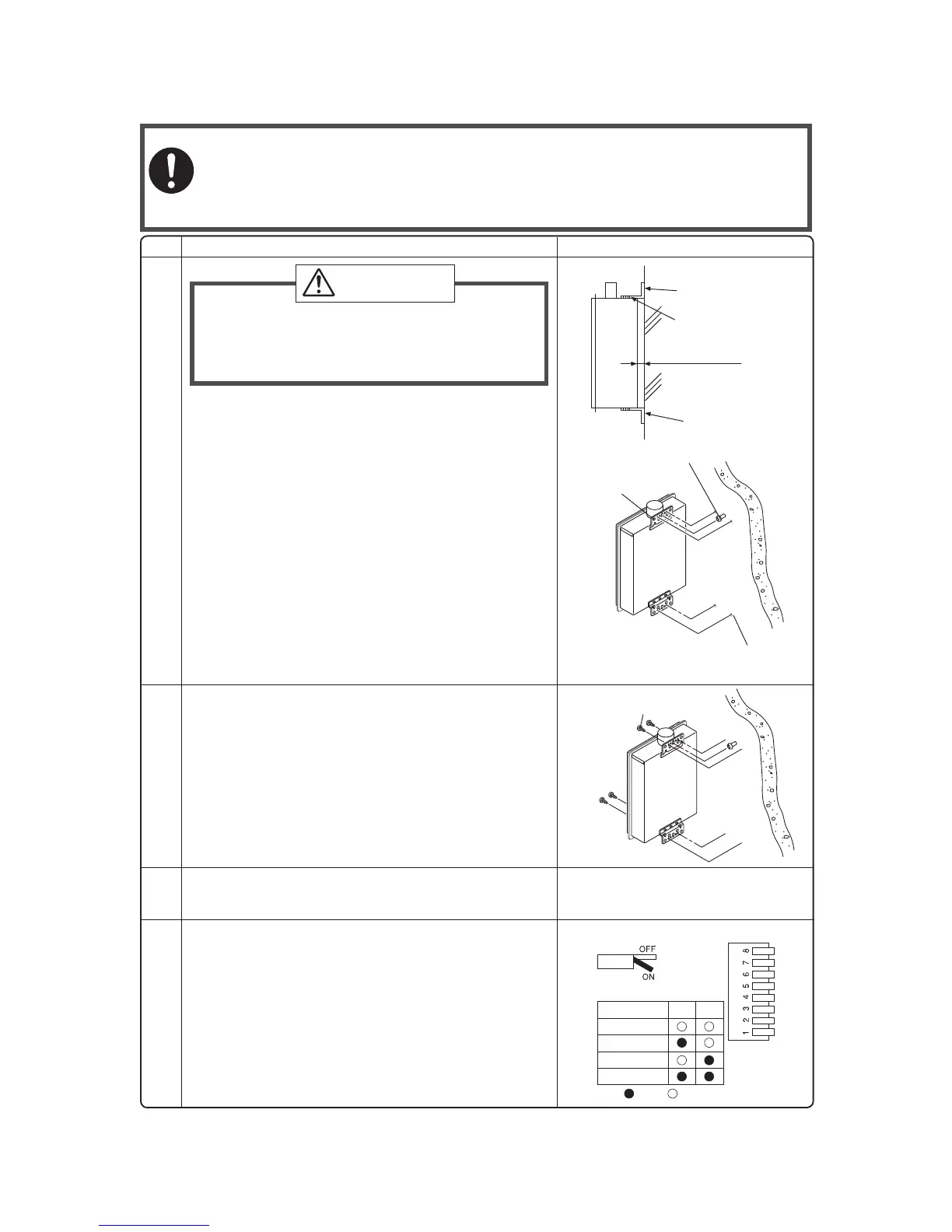
6. Drill holes for the remaining four screws.
7. Hang the unit again by the fi rst screw, and then
insert and tighten the remaining four screws.
8. Take waterproofi ng measures so that water does
not enter the building from screws mounting the
device.
• Make sure the unit is installed securely so that it will
not fall or move due to vibrations or earthquakes.
• The distance between the unit and the wall can be
adjusted within the range of 0.4 - 1.8" (10 - 46mm).
Adjust the brackets as necessary to accommodate
the vent system (factory default is 0.4" (10mm)).
1.
Loosen the four screws in the mounting bracket (upper),
match the desired mark to the back of the unit, and
then tighten the screws.
2.
Loosen the four screws in the mounting bracket (lower) and
secure it in the same position as the upper mounting bracket.
3. Drill a single screw hole, making sure to hit a stud.
4. Insert and tighten the screw and hang the unit by
the upper wall mounting bracket.
5.
Determine the positions for the remaining four screws
(two for the top bracket and two for the bottom), and
remove the unit.
• The weight of the device will be applied to the wall. If the strength of the wall is not suffi -
cient, reinforcement must be done to prevent the transfer of vibration.
• Do not drop or apply unnecessary force to the device when installing. Internal parts may
be damaged and may become highly dangerous.
• Install the unit on a vertical wall and ensure that it is level.
Locating Screw Holes
Mounting
Structure
• When installing with bare hands, take caution to
not infl ict injury.
• Be careful not to hit electrical wiring, gas, or water
piping while drilling holes.
Item
CAUTION
Be sure to do
Mounting Bracket
(upper)
Tapping Screw
Location of Screw Hole
Locating Screw Holes
Installations at Elevations
Above 2,000 ft.(610m).
• Adjust the dip switches as illustrated in the table to
the right if this water heater is installed at an altitude
of 2000 ft. (610m) or higher.
• Disconnect power to the water heater before chang-
ing the dip switches. Failure to perform this step will
result in a "73" code displayed on the remote control-
ler and a cease in operation. If this occurs, discon-
nect, then reconnect power to the water heater to
reset the system.
Note : Please refer to page 23 for the location of the
dip switch bank.
0.4 - 1.8"
(10 - 46mm)
mounting bracket
(upper)
mounting bracket
(lower)
mark
(0.4" (10mm) intervals)
* Do not change any other dipswitches.
* High elevation adjustment.
Standard
65
2,000 ft (610m)
ON= OFF=
4,000 ft (1,220m)
6,000 ft (1,830m)
 Loading...