DE
EN
NL
FR
DA
SV
EN
DE
SWIMMING POOL HEAT PUMP TYPE PXSWIMMING POOL HEAT PUMP TYPE PX
24
25
Alterations which serve the technological progress as well as errors excepted! ORIGINAL MANUAL NORSUPWWW.NORSUP.EU Alterations which serve the technological progress as well as errors excepted!
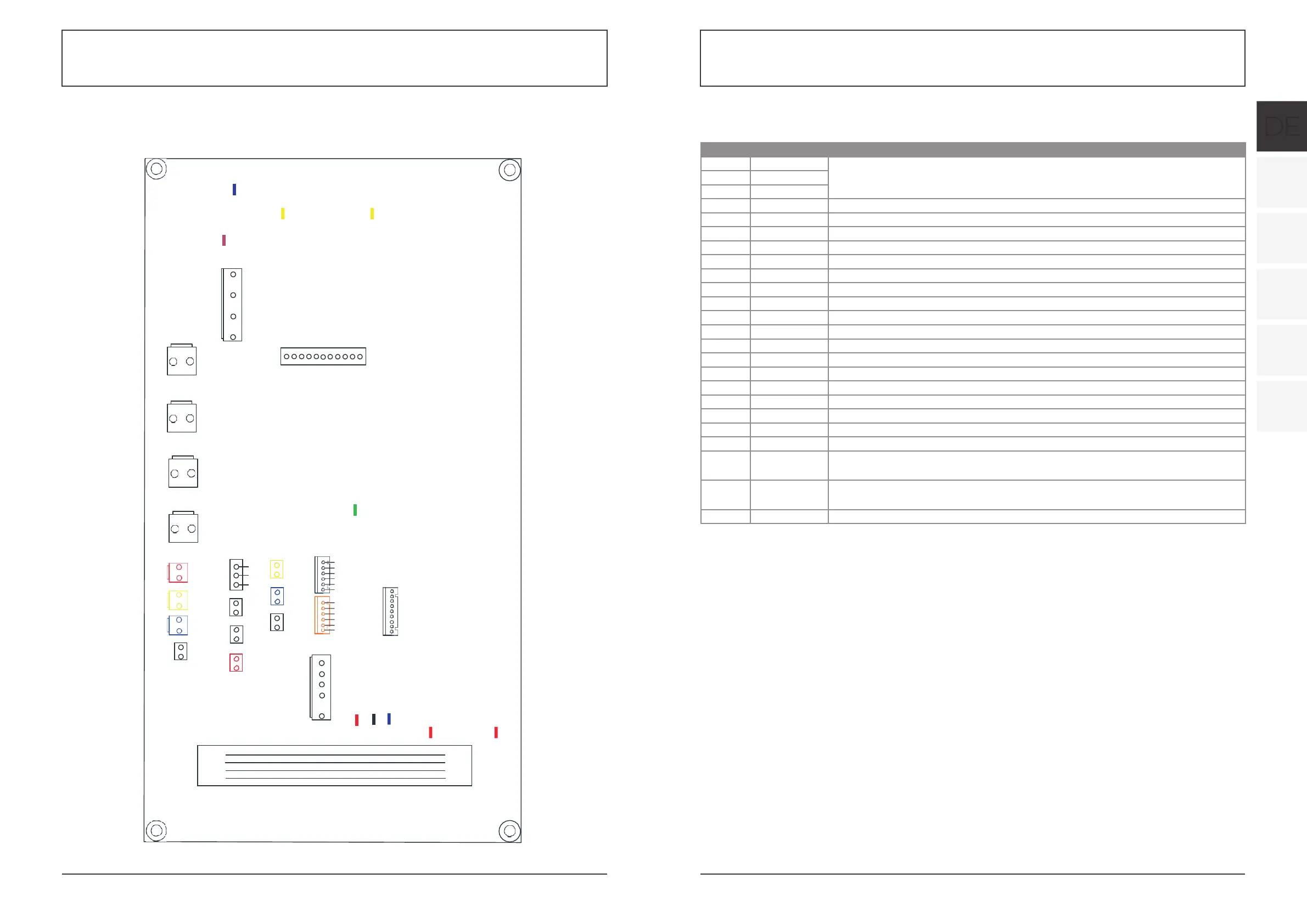
Controller interface diagram and definition Main board of the input and output interface instructions below
Number Sign Meaning
01 P10-(U)
02 P10-(V) Compressor (output 220-230VAC)
03 P10-(W)
04 CN18(EMV) Water pump (output 220-230VAC)
05 CN13(HEAT) 4-way valve (output 220-230VAC)
06 CN96(H) High speed of fan (output 220-230VAC)
07 CN96(L) Low speed of fan (output 220-230VAC)
08 P1 (AC-L) Live wire (input 220-230VAC)
09 P2(AC-N) Neutral wire (input 220-230VAC)
10 CN99(PL) Pressure sensor
11 CN29(OVT) Water flow switch (input)
12 CN30(HP) High pressure switch (input)
13 CN31 (LP) Low pressure switch (input)
14 CN7(OAT) System suction temperature (input)
15 CN21 (RES1) Water input temperature (input)
16 CN22(RES2) Water output temperature (input)
17 CN8(OPT) System fan coil temperature (input)
18 CN12(PH) Ambient temperature (input)
19 CN9(OHT) System Exhaust temperature (input)
20 POO(GND) Earth wire
21 P01(GND) Earth wire
22
P13(L)
P14(L)
Electric reactor
23
R485(B)
R485(A)
Color line controller communication
24 CN15 Electronic expansion valve
CN30(HP)CN31(LP)
CN7(OAT)
CN8(OPT) CN99(PL)
GND 0-5V IN 5V
CN22(RES2
C
)
N9(OHT)
CN12(PH)
D C B A 12V12V D C B
A
12V
12V
T-
TOOL0
EVDD
CN401
'(
Controller interface diagram and definition