DE
EN
NL
FR
DA
SV
EN
DE
SWIMMING POOL HEAT PUMP TYPE PXSWIMMING POOL HEAT PUMP TYPE PX
34
35
Alterations which serve the technological progress as well as errors excepted! ORIGINAL MANUAL NORSUPWWW.NORSUP.EU Alterations which serve the technological progress as well as errors excepted!
34
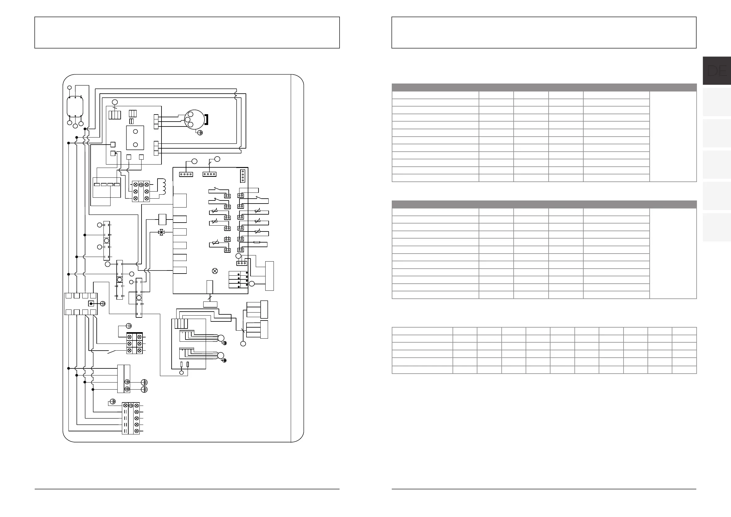
6.APPENDIX
6.1 Circuit diagram
CODE˖20181109-0009
K2
N
1
3
24
5
6
7
8
01
N
L
N
N
N
N
N
4V
1
3
24
5
6
7
8
02
N
L
Y/G
YEL
P
N
L
N
RED
BLU
TO PUMP
<10A
$
*1'
9
%
3
:89
3
3(
$&1 $&/
/ /
&1
&1
&1
&1
&1
&1
3
3
/
1
8
9
:
$&,:0
COMP
8
9
:
U
W
V
RED
BLK
WHT
PTC
K2
N
N
N
1
3
24
5
6
7
8
03
L4
/
/
/
3
L
1
KM1
L
N
N
KM1˖Contactor of compressor
SUT˖Suction temperature
AT˖Ambient temperature
COMP˖Compressor
CT˖Coil temperature
FM˖Fan motor
IT˖Inlet water temperature
LP˖Low pressure protection
OT˖Outlet water temperature
FS˖Flow switch
HP˖High pressure protection
EEV˖Electronic expansion valve
4V˖4 way valve
ET˖Exhaust temperature
PM˖Phase monitor
K2˖Relay of pump
K2
1
N
N
L
L
$&/RXW
$&1RXW$&1LQ
$&/LQ
(0,
CN1
FM1
ZL10
1
GND
485A1
12V
N
L
485B1
Y/G
WHT
BLK
CN4
L
/
4V
4
RED
BLK
WHT
Pressure sensor
᧤SUT᧥
CN9
3
RLY1
OUT2
OUT3
AC-N1
OUT4
OUT5
CN2
PC1004
CN8
4
CN13
A1A3A5A7A9
A11
t
5K
SUT LP
Remote
ON/OFF
A4A6A8A10
A12
A2
FS
HP
t
5K
IT
t
5K
CTET
t
50K
t
5K
OT
t
5K
AT
6.8K
CN11
A13
GND
GND
GND
GND
+12V
0~10V-OUT
PWM-IN
PWM-OUT
9
9
L
N
L
/
KM1
LN
LN
EEV
5
Y/G
FM2
Y/G
3
/
L
L
N
1
L
N
N
4
Controller
YEL 485B-
BLK GND
RED 12V
WHT 485A+
YEL 485B-
BLK GND
RED 12V
WHT 485A+
WIFI
220-240V~/50Hz
TO POWER
SUPPLY
4
HOHFWULFUHDFWRU
/
/
L
N
P35X/32
P26X/32
R
S
T
N
RED
BLK
WHT
BLU
RS
T
N
R
N
4V
1
3
24
5
6
7
8
02
N
N14
N
N
N
N
N
N
K2
4V
N
R
1
3
24
5
6
7
8
01
L3(C)
L2(B)
L1(A) 11
14
12
PM
N
N14
R
R
R
4
CODE˖20181109-0010
RED
BLK
WHT
Pressure sensor
᧤SUT᧥
Y/G
&203
8
9
:
8
9
:
K2
'ULYHUPRGXOHERDUG
DCN-IN
8 9:567
DCP-IN
DCN-OUT
DCP-OUT
B
A
GND
12V
CN602
GND
CN605
5V
JP601
HOHFWULFUHDFWRU
5
6
7
RED
BLK
WHT
R
S
T
N
1
N
1
R
RST
DC+
DC1+
DC-
DC1-
EEV
5
CN9
3
RLY1
OUT2
OUT3
AC-N1
OUT4
OUT5
CN2
PC1004
CN8
4
A1A3A5A7A9
A11
t
5K
SUT LP
Remote
ON/OFF
A4A6A8A10
A12
A2
FS
HP
t
5K
IT
t
5K
CTET
t
50K
t
5K
OT
t
5K
AT
6.8K
CN11
A13
GND
GND
GND
GND
+12V
0~10V-OUT
PWM-IN
PWM-OUT
9
9
$ % & 1
1&%$
(0,
),
4
TO POWER SUPPLY
380-415V/3N~/50Hz
CN1
FM1
ZL10
5
1
GND
485A1
12V
N
L
485B1
Y/G
WHT
BLK
CN4
FM2
Y/G
YEL
4
Controller
YEL 485B-
BLK GND
RED 12V
WHT 485A+
CN13
L
N
1
3
24
5
6
7
8
03
S
T
S
S
5
6 7
T
T
6
7
5
5
N
L1N
R
S
T
SPD
L2L3
N
N
K2
P
Y/G
N
TO PUMP
<10A
T
YEL 485B-
BLK GND
RED 12V
WHT 485A+
WIFI
K2˖Relay of pump
SUT˖Suction temperature
AT˖Ambient temperature
COMP˖Compressor
CT˖Coil temperature
FM˖Fan motor
IT˖Inlet water temperature
LP˖Low pressure protection
OT˖Out let water temperature
FS˖Flow switch
HP˖High pressure protection
EEV˖Electronic expansion valve
4V˖4 way valve
ET˖Exhaust temperature
PM˖Phase monitor
SPD˖Surge protection device
P35TX/32P26TX/32
6.2 CABLE SPECIFICATION
(1) Single phase unit
(2) Three phase unit
When the unit will be installed at outdoor, please use the cable which can against UV.
6.3 COMPARISON TABLE OF REFRIGERANT SATURATION TEMPERATURE
Nameplate maximum current Phase line Earth line MCB Creepage protector Signal line
No more than 10A 2×1.5mm
2
1.5mm
2
20A 30mA less than 0.1 sec
10~16A 2×2.5mm
2
2.5mm
2
32A 30mA less than 0.1 sec
16~25A 2×4mm
2
4mm
2
40A 30mA less than 0.1 sec
25~32A 2×6mm
2
6mm
2
40A 30mA less than 0.1 sec
32~40A 2×10mm
2
10mm
2
63A 30mA less than 0.1 sec
40 ~63A 2×16mm
2
16mm
2
80A 30mA less than 0.1 sec n×0.5mm
2
63~75A 2×25mm
2
25mm
2
100A 30mA less than 0.1 sec
75~101A 2×25mm
2
25mm
2
125A 30mA less than 0.1 sec
101~123A 2×35mm
2
35mm
2
160A 30mA less than 0.1 sec
123~148A 2×50mm
2
50mm
2
225A 30mA less than 0.1 sec
148~186A 2×70mm
2
70mm
2
250A 30mA less than 0.1 sec
186~224A 2×95mm
2
95mm
2
280A 30mA less than 0.1 sec
Nameplate maximum current Phase line Earth line MCB Creepage protector Signal line
No more than 10A 3×1.5mm
2
1.5mm
2
20A 30mA less than 0.1 sec
10~16A 3×2.5mm
2
2.5mm
2
32A 30mA less than 0.1 sec
16~25A 3×4mm
2
4mm
2
40A 30mA less than 0.1 sec
25~32A 3×6mm
2
6mm
2
40A 30mA less than 0.1 sec
32~40A 3×10mm
2
10mm
2
63A 30mA less than 0.1 sec
40 ~63A 3×16mm
2
16mm
2
80A 30mA less than 0.1 sec n×0.5mm
2
63~75A 3×25mm
2
25mm
2
100A 30mA less than 0.1 sec
75~101A 3×25mm
2
25mm
2
125A 30mA less than 0.1 sec
101~123A 3×35mm
2
35mm
2
160A 30mA less than 0.1 sec
123~148A 3×50mm
2
50mm
2
225A 30mA less than 0.1 sec
148~186A 3×70mm
2
70mm
2
250A 30mA less than 0.1 sec
186~224A 3×95mm
2
95mm
2
280A 30mA less than 0.1 sec
Pressure (MPa) 0 0.3 0.5 0.8 1 1.3 1.5 1.8 2 2.3
Temperature (R410A)(°C) -51.3 -20 -9 4 11 19 24 31 35 39
Temperature (R32)(°C) -52.5 -20 -9 3.5 10 18 23 29.5 33.3 38.7
Pressure (MPa) 2.5 2.8 3 3.3 3.5 3.8 4 4.5 5 5.5
Temperature (R410A)(°C) 43 47 51 55 57 61 64 70 74 80
Temperature (R32)(°C) 42 46.5 49.5 53.5 56 60 62 67.5 72.5 77.4