DE
EN
NL
FR
DA
SV
EN
DE
SWIMMING POOL HEAT PUMP TYPE PXSWIMMING POOL HEAT PUMP TYPE PX
30
31
Alterations which serve the technological progress as well as errors excepted! ORIGINAL MANUAL NORSUPWWW.NORSUP.EU Alterations which serve the technological progress as well as errors excepted!
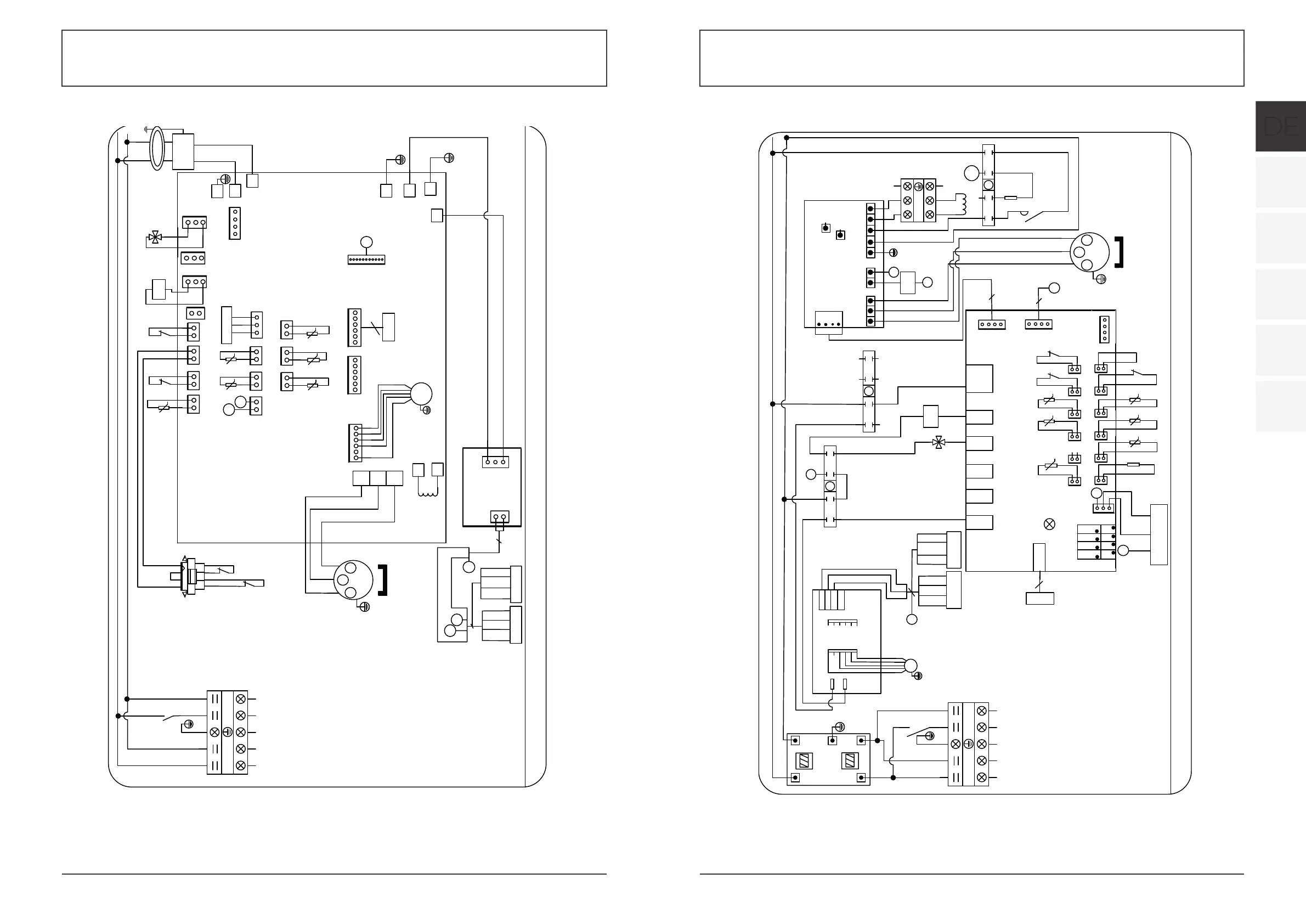
6.APPENDIX
6.1 Circuit diagram
33
CODE˖20181109-0005
K2
N
1
3
24
5
6
7
8
01
N
L
N
N
N
N
N
4V
1
3
24
5
6
7
8
02
N
L
Y/G
YEL
P
L
N
RED
BLU
$
*1'
9
%
3
:89
3
3(
$&1 $&/
/ /
&1
&1
&1
&1
&1
&1
3
3
/
1
8
9
:
$&,:0
COMP
8
9
:
U
W
V
RED
BLK
WHT
PTC
K2
N
N
N
1
3
24
5
6
7
8
03
L4
/
/
/
3
L
3
1
K1
L
N
N
K1˖Relay of compressor
SUT˖Suction temperature
AT˖Ambient temperature
COMP˖Compressor
CT˖Coil temperature
FM˖Fan motor
IT˖Inlet water temperature
LP˖Low pressure protection
OT˖Outlet water temperature
FS˖Flow switch
HP˖High pressure protection
EEV˖Electronic expansion valve
4V˖4 way valve
ET˖Exhaust temperature
PM˖Phase monitor
K2˖Relay of pump
P20X/32
K2
1
N
N
L
L
$&/RXW
$&1RXW
$&1LQ
$&/LQ
(0,
CN1
FM1
ZL10
1
GND
485A1
12V
N
L
485B1
Y/G
WHT
BLK
CN4
L
/
4V
4
RED
BLK
WHT
Pressure sensor
᧤SUT᧥
CN9
3
RLY1
OUT2
OUT3
AC-N1
OUT4
OUT5
CN2
PC1004
CN8
4
CN13
A1A3A5A7A9
A11
t
5K
SUT LP
Remote
ON/OFF
A4A6A8A10
A12
A2
FS
HP
t
5K
IT
t
5K
CTET
t
50K
t
5K
OT
t
5K
AT
6.8K
CN11
A13
GND
GND
GND
GND
+12V
0~10V-OUT
PWM-IN
PWM-OUT
9
9
L
/
K1
EEV
5
LN
1
2
4
N
L
N
220-240V~/50Hz
TO POWER
SUPPLY
TO PUMP
<10A
4
Controller
YEL 485B-
BLK GND
RED 12V
WHT 485A+
WiFi
BLK GND
YEL 485B-
WHT 485A+
RED 12V
HOHFWULFUHDFWRU
L
N
/
/
/
R
S
T
N
RED
BLK
WHT
BLU
RS
T
N
R
N
4V
1
3
24
5
6
7
8
02
N
N14
N
N
N
N
N
N
K2
4V
N
R
1
3
24
5
6
7
8
01
L3(C)
L2(B)
L1(A) 11
14
12
PM
N
N14
R
R
R
4
CODE˖20181109-0007
RED
BLK
WHT
Pressure sensor
᧤SUT᧥
Y/G
&203
8
9
:
8
9
:
K2
'ULYHUPRGXOHERDUG
DCN-IN
8 9:567
DCP-IN
DCN-OUT
DCP-OUT
B
A
GND
12V
CN602
GND
CN605
5V
JP601
HOHFWULFUHDFWRU
5
6
7
RED
BLK
WHT
R
S
T
N
1
N
1
R
RST
P20TX/32
DC+
DC1+
DC-
DC1-
EEV
5
CN9
3
RLY1
OUT2
OUT3
AC-N1
OUT4
OUT5
CN2
PC1004
CN8
4
A1A3A5A7A9
A11
t
5K
SUT LP
Remote
ON/OFF
A4A6A8A10
A12
A2
FS
HP
t
5K
IT
t
5K
CTET
t
50K
t
5K
OT
t
5K
AT
6.8K
CN11
A13
GND
GND
GND
GND
+12V
0~10V-OUT
PWM-IN
PWM-OUT
9
9
$ % & 1
1&%$
(0,
),
4
TO POWER SUPPLY
380V/3N~/50Hz
CN1
FM1
ZL10
5
1
GND
485A1
12V
N
L
485B1
Y/G
WHT
BLK
CN4
YEL
4
Controller
YEL 485B-
BLK GND
RED 12V
WHT 485A+
CN13
L
N
1
3
24
5
6
7
8
03
S
T
S
S
5
6 7
T
T
6
7
5
5
N
L1N
R
S
T
SPD
L2L3
N
N
K2
P
Y/G
N
TO PUMP
<10A
T
WIFI
YEL 485B-
BLK GND
RED 12V
WHT 485A+
K
2˖Relay of pump
SUT˖Suction temperature
AT˖Ambient temperature
COMP˖Compressor
CT˖Coil temperature
F
M˖Fan motor
IT˖Inlet water temperature
LP˖Low pressure protection
OT˖Outlet water temperature
FS˖Flow switch
HP˖High pressure protection
EEV˖Electronic expansion valve
4
V˖4 way valve
ET˖Exhaust temperature
PM˖Phase monitor
SPD˖Surge protection
device
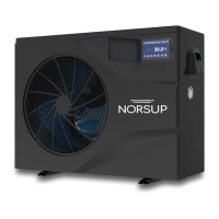
6.APPENDIX
6.1 Circuit diagram
32
8:
LN
1
2
L
N
RED
BLU
Y/G
K2
CN21
RES1
CN29
OVT
CN30
HP
CN31
LP
CN13
HEAT
CN18
EMV
CN66
RY
CN11
FOUR
CN96
OT(RED)
3/
3/
CN7
OAT
CN8
OPT
CN22
RES2
CN9
OHT
CN12
PH
FS LP
A B
RS485
CN15
LEV1
CN24
LEV2
AT(WHT)
4V
K2
$&/
$&1
L
N
*1'
A
B
reactor
EEV
5
*1'
COMP
8
9
:
U
W
V
RED
BLK WHT
FM
9
CODE˖20190330-0001
FILTER
L
BLU
BRN
N
A
B
RED
WHT
YEL
BLK
$&/
$&1
IT(BLU)
SUT(GRN)
CT(YEL)
Magetic ring
HP
HP
EP
EP
HP
EP
GRN
t
50K
ET(GRY)
DCFAN
CN97
SPS
CN2 CN1
2AC32I12WO1
L
N
P
N
220-240V~/50Hz
TO POWER
SUPPLY
TO PUMP
<10A
CN99
PL
RED
WHT
BLK
PS
3
BRN
BLU
t
5K
t
5K
t
5K
t
5K
t
5K
OT˖Outlet water temperature
4V˖4 way valve
AT˖Ambient temperature
COMP˖Compressor
CT˖Coil temperature
FM˖Fan motor
IT˖Inlet water temperature
LP˖Low pressure protection
FS˖Flow switch
HP˖High pressure protection
ET˖Exhaust temperature
EEV˖Electronic expansion valve
SPS˖Switching power supply
K2˖Realy of pump
EP˖Exhaust protection
SUT˖Suction temperature
PS˖Pressure sensor
CN10
G
2
G
4V 4V
4
YEL 485B-
RED 12V
WHT 485A+
BLK GND
WiFi
BLK GND
YEL 485B-
WHT 485A+
RED 12V
Controller
P13X/32
8:
LN
1
2
L
N
RED
BLU
Y/G
K2
CN21
RES1
CN29
OVT
CN30
HP
CN31
LP
CN13
HEAT
CN18
EMV
CN66
RY
CN11
FOUR
CN96
OT(RED)
3/
3/
CN7
OAT
CN8
OPT
CN22
RES2
CN9
OHT
CN12
PH
FS LP
A B
RS485
CN15
LEV1
CN24
LEV2
AT(WHT)
4V
K2
$&/
$&1
L
N
*1'
A
B
reactor
EEV
5
*1'
COMP
8
9
:
U
W
V
RED
BLK WHT
FM
9
˖
FILTER
L
BLU
BRN
N
A
B
RED
WHT
YEL
BLK
$&/
$&1
IT(BLU)
SUT(GRN)
CT(YEL)
Magetic ring
HP
HP
EP
EP
HP
EP
GRN
t
50K
ET(GRY)
DCFAN
CN97
SPS
CN2 CN1
2AC32I12WO1
L
N
P
N
220-240V~/50Hz
TO POWER
SUPPLY
TO PUMP
<10A
CN99
PL
RED
WHT
BLK
PS
3
4
YEL 485B-
RED 12V
WHT 485A+
BLK GND
WiFi
BLK GND
YEL 485B-
WHT 485A+
RED 12V
BRN
BLU
t
5K
t
5K
t
5K
P17X/32
t
5K
t
5K
Controller
CN10
G
2
G
OT˖Outlet water temperature
4V˖4 way valve
AT˖Ambient temperature
COMP˖Compressor
CT˖Coil temperature
FM˖Fan motor
IT˖Inlet water temperature
LP˖Low pressure protection
FS˖Flow switch
HP˖High pressure protection
ET˖Exhaust temperature
EEV˖Electronic expansion valve
SPS˖Switching power supply
K2˖Realy of pump
EP˖Exhaust protection
SUT˖Suction temperature
PS˖Pressure sensor