9
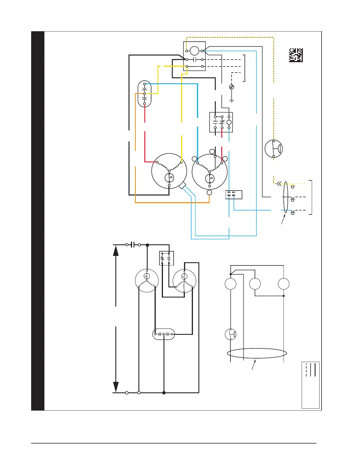
Figure 5. Wiring Diagram for *SA3BE4M (5 Ton Units)
YELLOW/
BLACK
Y2 CY
L1 L2
T1 T2
CONTACTOR
HIGH PRESSURE
SWITCH
OUTDOOR
FAN MOTOR
COMPRESSOR
TO THERMOSTAT
YELLOW/
BLACK
GRND L1 L2
SINGLE PHASE
FIELD SUPPLY
GROUNDING
SCREW
BLUE
YELLOW
BLACK
RED
ORANGE
C
S
R
HC F
L
S
C
H
COMNO
FAN
RELAY
NC
LFT
RT
CAPACITOR
BLACK
BLACK
C
D
TERMINAL
BLOCK
BLUE
BLACK
RED
YELLOW
CC- Contactor Coil
CSC - Compressor Solenoid Coil
HPS - High Pressure Switch
OFR - Outdoor Fan Relay Coil
C
Y2
Y
HPS
24 VOLT FIELD
CONNECTIONS
208/230VTwo Stage Split Air Conditioner (Outdoor Section)
With Two Speed Outdoor Fan Motor
Single Phase / 60 Hz.
WIRING DIAGRAM
1043682A
(REPLACES 10436820)
2/23
FIELD WIRING
LEGEND:
LOW VOLTAGE
HIGH VOLTAGE
BLACK
BLUE
BLUE
BLUE
208/230V
H
C
F
R
C
S
S
C
H
L2
T2
COMPRESSOR
CONTACTS
L1
T1
COMPRESSOR
FAN MOTOR
L
FAN RELAY
CC
OFR
NOTES:
1. Disconnect all power before servicing.
2. For supply connections use copper conductors only.
3. Not suitable on systems that exceed 150 volts to ground.
4. For replacement wires use conductors suitable for 105°C
5. For ampacities and overcurrent protection, see unit rating plate.
6. Connect to 24 vac/40va/class 2 circuit. See furnace/airhandler installation
instructions for control circuit and optional relay/transformer kits.
7. Caution: The Low Voltage wiring shall NOT be grounded to this unit.
1. Couper le courant avant
de faire letretien.
2. Employez uniquement des
conducteurs en cuivre.
3. Ne convient pas aux installations
de plus de 150 volt a la terre.
CAPACITOR
SEE NOTES
6 AND 7
SEE NOTES
6 AND 7
CSC
 Loading...