6
until the condition returns to normal or if 24 VAC power
is removed from the module. See Table 10 (page 18) for
flash code identification or Table 11 (page 19) for module
wiring troubleshooting.
LED Description
• POWERLED(Green):indicatesvoltageispresentat
the power connection of the module.
• ALERT LED (Yellow): communicates an abnormal
system condition through a unique flash code.
NOTE: The ALERT LED will flash consecutively, pause
and then repeat the process. The number of consecutive
flashes, referred to as the Flash Code, correlates to a
particular abnormal condition. Detailed descriptions of
these ALERT Flash Codes are listed in Tables 10 & 11.
• TRIPLED(Red):indicatesademandsignalisreceived
from the thermostat, but current to the compressor is
not detected by the module. The TRIP LED typically
indicates if the compressor protector is open or the
compressor has no power.
The scroll compressor’s R (run), C (common), and S
(start) wires are routed through the holes in the Comfort
Alert
TM
module marked R, C, & S. NOTE: The common
wire does not need to be routed through the module for
it to operate.
Example
:
AB = 226V
BC = 230V
AC = 227V
2. Determine the average voltage in the power supply.
3. Determine the maximum deviation:
4. Determine percent of
voltage imbalance by
using the results from
steps 2 & 3 in the following
equation.
2
228
100
x
= 0.88%
Example:
1. Measure the line voltages
of your 3 phase power
supply where it enters the
building and at a location
that will only be dedicated
to the unit installation (at
the units circuit protection
or disconnect).
Unbalanced 3-Phase Supply Voltage
Voltage unbalance occurs when the voltages of all phases
of a 3-phase power supply are no longer equal. This
unbalance reduces motor efficiency and performance.
Some underlying causes of voltage unbalance may include:
Lack of symmetry in transmission lines, large single-phase
loads, and unbalanced or overloaded transformers. A
motor should never be operated when a phase imbalance
in supply is greater than 2%.
Perform the following steps to determine the percentage
of voltage imbalance:
In this example, the measured line voltages were
226, 230, and 227. The average would be 228 volts
(226 + 230 + 227 = 683 / 3 = 228).
The amount of phase imbalance (0.88%) is satisfactory
since the amount is lower than the maximum allowable
2%. Please contact your local electric utility company if
your voltage imbalance is more than 2%.
Example:
From the values given in step 1, the BC voltage
(230V) is the greatest difference in value from
the average:
230 - 228 = 2
228 - 226 = 2
228 - 227 = 1
Highest Value
fromaverage voltage
=100 x
averagevoltage
% Voltage Imbalance
Grounding
WARNING:
The unit cabinet must have an uninterrupted or
unbroken electrical ground to minimize personal
injury if an electrical fault should occur. Do not
use gas piping as an electrical ground
!
This unit must be electrically grounded in accordance
with local codes or, in the absence of local codes, with
the National Electrical Code (ANSI/NFPA 70) or the CSA
C22.1 Electrical Code. Use the grounding lug provided in
the control box for grounding the unit.
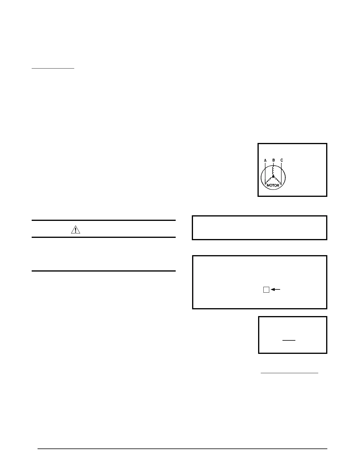
Reverse Rotation Verification
After making all of the power connections to the unit, the
rotation of the compressor must be checked. If the rotation
is in the wrong direction, the compressor will make an
abnormally loud noise. To check the rotation perform the
following steps:
1. Make sure the outside power disconnect is in the OFF
position.
2. Set the indoor thermostat to a set point that will call for
cooling.
3. Retun to the outside power disconnect and switch it
to the ON position. If the compressor is making an
abnormally loud noise, immediately switch the outside
power disconnect to the OFF position.
4. Switch any two of the three power leads at the power
connections to the unit.
5. SetReturn to the outside power disconnect and swith
it to the ON position.
6. Verify that the compressor is now running properly.