7
2. Verify the blower runs continuously. Check the air delivery
at the supply registers and adjust register openings for
balanced air distribution. If insufficient air is detected,
examine ductwork for leaks or obstructions.
3. Set the thermostat fan mode to AUTO and verify the
blower stops running.
System Cooling
1. Set the thermostat’s system mode to COOL and the
fan mode to AUTO. Gradually lower the thermostat
temperature setpoint below room temperature and
verifytheoutdoorunitandindoorblowerenergize.
2. Verify blower wheel is spinning in direction indicated by
arrow. Feel the air being circulated by the indoor blower
and verify that it is cooler than ambient temperature.
Listen for any unusual noises. If unusual sounds occur,
determine the source of the noise and correct as
necessary.
3. Verify HI and LO refrigerant pressures.
4. Allow the system to operate for several minutes and then
set the temperature selector above room temperature.
Verify the fan and compressor cycle off with the
thermostat. NOTE: The blower should also stop unless
fan mode is set to the ON position.
System Heating (optional)
1. Set the thermostat's system mode to HEAT and the
temperature mode above room temperature.
2. Verify the optional heating equipment (furnace or
electricheat)andindoorblowerenergize.Feeltheair
being circulated by the indoor blower and verify that
it is warmer than ambient temperature. Listen for any
unusual noises. If unusual sounds occur, determine the
source of the noise and correct as necessary.
Refrigerant Charging
WARNING:
S4BD Split System Air Conditioners are shipped
charged with R410A refrigerant and ready
for installation. If repairs make it necessary
for evacuation and charging, it should only
be attempted by qualified trained personnel
thoroughly familiar with this equipment. Under
no circumstances should the owner attempt to
install and/or service this equipment. Failure to
comply with this warning could result in property
damage, personal injury, or death.
After refrigerant line connections are completed, it is
required that you leak check and evacuate the indoor
section and all line connections (using proper methods)
beforenalizingthefullsystemrefrigerantcharge.
• Refrigerant charging charts are applicable only to
matched assemblies of NORDYNE equipment and
listed airflows for the indoor coil. Refer to Tables 3 - 9
START UP & ADJUSTMENTS
Pre-Start Check List
√ Verify the indoor unit is level and allows proper
condensate drainage.
√ Verify the outdoor coil and top of the unit are free from
obstructions and debris, and all equipment access/
control panels are in place.
√ Verify air filters are cleaned and properly installed.
√ Verify duct work is sealed to prevent air leakage.
√ Verify line voltage power leads are securely connected
and the unit is properly grounded.
√ Verify low voltage wires are securely connected to the
correct leads on the low voltage terminal strip.
√ Verify power supply branch circuit overcurrent protection
issizedproperly.
√ Verify the thermostat is wired correctly.
Start-Up Procedures
The thermostat's function mode should be set to OFF and
the fan mode should be set to AUTO. Close all electrical
disconnectstoenergizethesystem.
Air Circulation - Indoor Blower
1. Set the thermostat system mode on OFF and the fan
mode to ON.
Thermostat Connections
• Thermostat connections should be made in accordance
with the instructions supplied with the thermostat and
the indoor equipment.
• The outdoor unit is designed to operate from a 24 VAC
Class II control circuit. The control circuit wiring must
comply with the current provisions of the NEC (ANSI/
NFPA 70) and with applicable local codes having
jurisdiction.
• The low voltage wires must be properly connected to
the units low voltage terminal block. Recommended
wire gauge and wire lengths for typical thermostat
connections are listed in Table 2.
• The thermostat should be mounted about 5 feet
above the floor on an inside wall. DO NOT install the
thermostat on an outside wall or any other location
where its operation may be adversely affected by radiant
heat from fireplaces, sunlight, or lighting fixtures, and
convective heat from warm air registers or electrical
appliances. Refer to the thermostat manufacturer’s
instruction sheet for detailed mounting and installation
information.
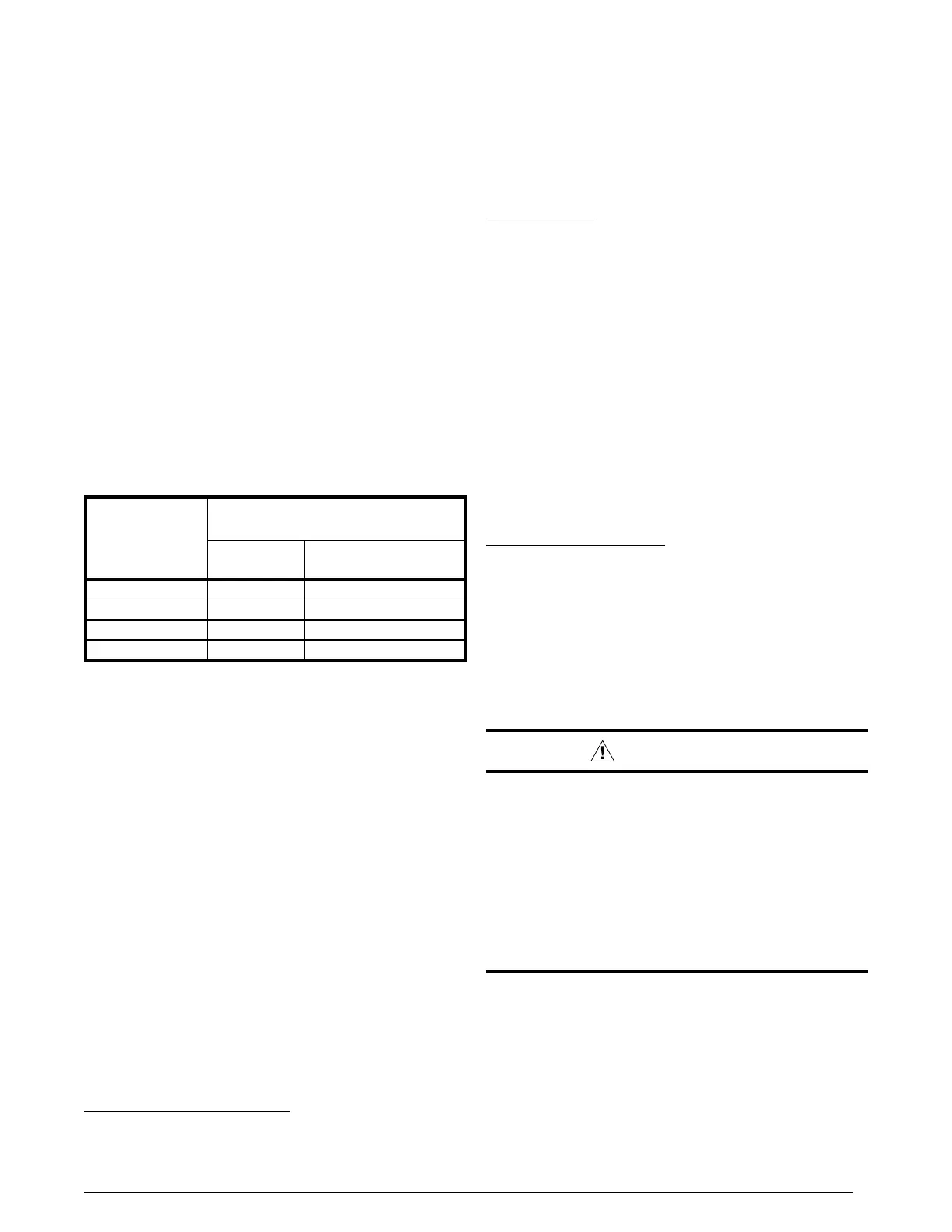
Table 2. Thermostat Wire Gauge
Thermostat
Wire Gauge
Recommended T-Stat Wire
Unit to T-Stat (Length in FT)
2-Wire
(Heating)
5-Wire
(Heating/Cooling)
24 55 25
22 90 45
20 140 70
18 225 110