EasyManua.ls Logo

Nortek TA Series - User Manual

Nortek TA Series
44 pages
Print Icon
To Next Page IconTo Next Page
Loading...
*TA Upflow / HorizonTAl fUrnAce
*TK Downflow fUrnAce
Two-STAge nonconDenSing gAS fUrnAceS wiTH fixeD & VAriAble SpeeD blowerS - 80+ AfUe
wArning / AVerTiSSeMenT
fire or exploSion HAzArD
   





       


wHAT To Do if YoU SMell gAS









riSQUe D’incenDie oU D’ exploSion




      


       


QUe fAire S’il Y A Une oDeUr De gAz

     








inSTAllATion inSTrUcTionS

Table of Contents

Question and Answer IconNeed help?

Do you have a question about the Nortek TA Series and is the answer not in the manual?

Overview

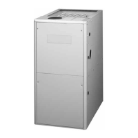
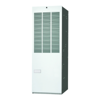
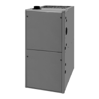
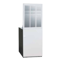
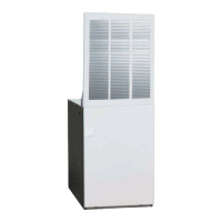
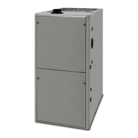
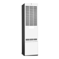
This document describes the installation, operation, and maintenance of two-stage non-condensing gas furnaces, specifically the *TA (Upflow/Horizontal) and *TK (Downflow) series, designed for residential heating applications.

Function Description:

These furnaces are two-stage, non-condensing gas furnaces that provide forced-air heating for residential buildings. They operate by burning natural gas or LP/propane to heat air, which is then circulated throughout the building by a blower. The two-stage operation allows for more efficient heating by running at a lower fire rate (first stage) for most heating demands and switching to a higher fire rate (second stage) for greater heating needs. This design aims to maximize heat exchanger life by ensuring combustion air is free of corrosive chemicals, ideally drawn from outdoors. The furnaces are designed for installation in various configurations including upflow, downflow, and horizontal, and can be integrated with cooling systems.

Important Technical Specifications:

  • Input Rate Deration: For altitudes above 2,000 feet, the appliance must be derated by 4% for each 1,000 feet of altitude.
  • Combustion Air Requirements:
    • Confined Space (Air from Inside): Each opening must have a free area of at least 1 square inch per 1,000 Btuh of total appliance input, but not less than 100 square inches. Openings must start no more than 12 inches from the top and bottom of the enclosure.
    • Confined Space (Outdoor Air from Crawl Space or Vented Attic): Each opening must have a minimum free area of 1 square inch per 4,000 Btuh of total appliance input.
    • Confined Space (Outdoor Air Using Vertical Ducts): Each opening and duct must have a minimum free area of 1 square inch per 4,000 Btuh of total appliance input.
    • Confined Space (Outdoor Air Using Horizontal Ducts): Each opening and duct must have a minimum free area of 1 square inch per 2,000 Btuh of total appliance input.
    • Air Directly Through An Exterior Wall: Two openings, each with a free area of at least 1 square inch per 4,000 Btuh of total appliance input.
    • Minimum dimension of any combustion air opening is 3 inches.
  • Clearances to Combustible Materials: Design Certified by CSA International for minimum clearances. A minimum of 24 inches clearance from the front of the unit is required, with 36 inches strongly recommended for servicing.
  • Venting: Category I venting. Horizontal vent systems require high-temperature sealant (450°F) and are not approved without an add-on power venter. Flexible vent systems are approved for lining existing masonry chimneys, provided they meet code requirements and are supported at no more than 5-foot intervals with a minimum slope of 1/4 inch per foot.
  • Electrical: Requires 115V, 60Hz, single-phase power. Minimum wire gauge for thermostat wiring is specified in Table 2.
  • Gas Supply: Must comply with National Fuel Gas Code (ANSI Z223.1) or CAN/CGA B149.1/.2. A manual main shut-off valve and drip leg are required.
  • Airflow Data: Tables are provided for heating/cooling airflows (CFM) and temperature rises (°F) for both fixed and variable speed blowers, across different external static pressures and motor switch settings. Two openings are required for airflows above 1,600 CFM.
  • Temperature Rise: Approximate values are provided, actual rises may vary. Shaded grey areas in tables are for reference only and not recommended.
  • Motor Control Boards: Two variations: fixed speed (controls torque) and variable speed (controls airflow at constant CFM). Both use the same furnace control board.
  • Autostaging: For single-stage thermostats, the furnace can automatically stage up to high fire after a period (8 or 12 minutes) in low fire. For two-stage thermostats, autostaging is disabled by default.

Usage Features:

  • Two-Stage Operation: Allows the furnace to operate at a lower capacity for most heating needs, improving efficiency and comfort, and switch to full capacity when demand is higher.
  • Autostaging (Single-Stage Thermostats): Enables single-stage thermostats to benefit from two-stage operation by automatically transitioning from low to high fire after a set delay (8 or 12 minutes).
  • Dehumidification Options: Both motor control boards have a DEHUM connection to reduce blower speed during cooling, increasing humidity removal. This can be wired to a room thermostat with a humidity sensor or a separate humidistat.
  • Thermostat Compatibility: Supports single-stage AC & single-stage thermostats, single-stage AC & two-stage thermostats, and two-stage AC & two-stage thermostats, with specific wiring configurations for each.
  • Operating Sequence: Detailed sequences for heating, cooling, and continuous fan modes are provided, including pre-purge, igniter warm-up, flame proving, blower delays, and post-purge cycles.
  • High Altitude Application: Requires specific orifice sizes and manifold pressures based on installation altitude and local gas heating value. Conversion kits are available for LP/Propane.

Maintenance Features:

  • Annual Inspection: Recommended annual inspection and cleaning by a qualified service technician to ensure continued safe operation and prevent soot buildup, corrosion, or other issues.
  • Burner Maintenance: Inspect burners for accumulated dust or debris and clean with a soft wire brush if necessary. Care must be taken not to damage the igniter.
  • Flue Passages Cleaning: Detailed steps for cleaning flue passages, including removing the burner assembly, inducer assembly, and collector pan, and using a wire brush and vacuum cleaner.
  • Vent System Check: Annually check the vent pipe and/or chimney for corrosion or blockages. Replace corroded sections and remove obstructions.
  • Blower Limit Switch: Manually resettable safety device. If tripped, requires identification and correction of the fault condition before resetting.
  • Flame Roll-Out Switch: Manually resettable safety device that indicates if burner flames are not properly drawn into the heat exchanger.
  • Pressure Switch: Verifies proper inducer operation and prevents furnace operation with flue blockage.
  • Supply Air Limit Switch: Prevents excessive outlet air temperature.
  • Lubrication: Blower motor and inducer blower bearings are pre-lubricated and sealed, requiring no further oiling for the life of the motor.
  • Troubleshooting Guide: Provides a checklist for common issues (thermostat, blower door, circuit breaker, gas supply, filter, flame sensor, LED fault codes) and their corresponding diagnostic descriptions and remedies.
  • Bottom Panel Removal: Instructions for removing the bottom panel for servicing, with an alternate method if the standard procedure is not feasible.

Nortek TA Series Specifications

General IconGeneral
BrandNortek
ModelTA Series
CategoryFurnace
LanguageEnglish

Related product manuals