·
Press Yes to continue. A confirmation dialog will display the deployment
parameters and allow you to verify that the set-up is what you intended.
·
Press Confirm to send the configuration to the instrument. The instrument will verify
that the deployment has started. The configuration information from the deployment
sequence is saved in a log file that has the same name as the deployment..
Stop Recorder Deployment
·
Select Stop Recorder Deployment. When data acquisition has stopped a dialog
will display the current instrument and PC clock time.
Data Retrieval
·
Select Recorder Data Retrieval.
·
The recorder overview dialog will show a list of all files currently stored in the
recorder, including the time of the first measurement and the size for each file.
·
Select a file in the list by clicking on the filename. Press Retrieve to specify the
name and disk location of the file.
Tip! Check the retrieved data before deploying the instrument for the second time. If
something is wrong with the instrument, the configuration or the deployment, this will
be detected and the possibility of making the same mistake twice is avoided.
Data Conversion
·
To convert binary data files retrieved from the recorder to a readable ASCII format,
select Data Conversion.
·
Add files to the Files to convert list by using the Add file... file selection dialog.
Select the file to convert in the list and press the blue arrow. Specify the location for
the converted files in the Save in folder field. An optional prefix or suffix that will be
added to the recorder filename may be specified. Select from the View files drop-
down list to open the converted (ASCII) files in e.g. Notepad.
On-line Data Collection
·
Select Start Data Collection from the On-line menu (or press the toolbar button) to
start data acquisition. The real time display shows velocity data and sensor data as
it is collected.
·
To capture the data that comes in over the serial port to disk select Disk
Recording… from the On-line menu and define the name of a file (without
extension). Once this disk file is defined, the Start Disk Recording and Stop Disk
Recording menu items and toolbar buttons will be enabled.
Mounting
Proper mounting of the instrument is crucial for successful collection of data. Please
mount the instrument in accordance with the Mounting Guidelines in the
Comprehensive Manual.
Cables
Our instruments are mostly shipped with RS232 communication. RS422 is used for
cables longer than 50 m. The wiring is shown in the tables below. The output can
either be in ASCII, in fixed NMEA format, or binary format. Communication baud rate:
300-115200 (user setting), recorder download baud rate: 600/1200 kBaud. Ensure
that the connectors and dummy plugs are lubricated with dielectric silicone. We
recommend 3M silicone spray. Note that the silicone grease included in the shipment
should be used on the O-rings only.
Analog Input (default for most instruments)
The instrument can read two analog inputs at the same time. The input range is 0-5V,
corresponding to 0-65535 counts in the data file.
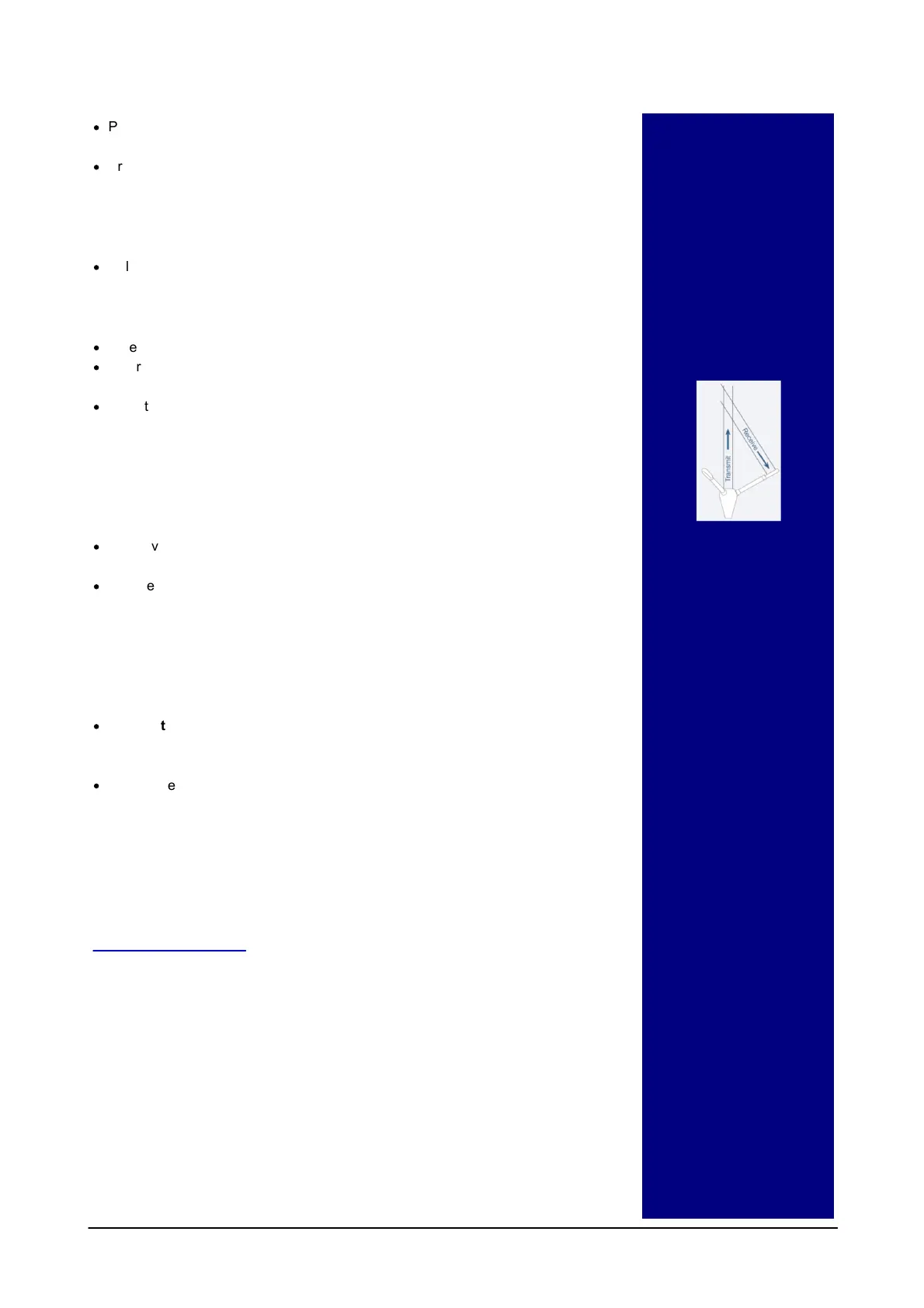
Basic principles
Pulse-coherent instruments
utilize a pair of acoustic pulses
w ith a know n time lag to
determine a Doppler induced
phase shift. This measured
phase shift is converted to
velocity by scaling w ith the
speed of sound in water. The
Vector use separate
transducers to transmit and
receive the acoustic beams
(bistatic system).
Measuring waves
The Vector can measure w aves
using the PUV method. The
pressure measurement provides
a means of estimating all the
nondirectional w ave
parameters, w hile the combined
P, U, and V measurements allow
for estimating the directional
w ave parameters. These data
need to be post processed.
Data analysis
The softw are supplied has been
designed to provide you w ith the
ability to set the instrument up
for deployment, upgrade the
firmw are, dow nload acquired
data and do a quality assurance
of them. The data can be
converted to ASCII format that
may be imported into various
post processing programs.

 Loading...