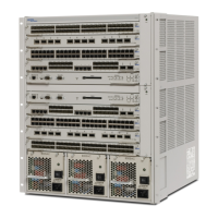
Do you have a question about the Nortel Passport 15000 and is the answer not in the manual?
Procedures for initial installation of NEBS 2000 frame, Passport 15000, Passport 20000, or Passport 15000-VSS.
Tasks and procedures to install or replace power and ground hardware for Passport 15000 or 20000.
Tasks to manage function processors (FPs) on your Passport switch.
Procedures related to control processors (CPs) including upgrade and replacement.
Procedures for replacing cooling units, fan controllers, fans, and temperature sensors.
Tasks and procedures related to BIP alarm module and external alarm cable replacement.
Overview of common personal safety considerations when working with a Passport switch.
Overview of common service loss risks when working with a Passport switch.
Overview of common equipment damage risks when working with a Passport switch.
Guidelines on preventing damage from electrostatic discharge (ESD).
Overview of common maintenance tasks including filter replacement and vacuuming.
Procedure to replace an FP cable promptly if it fails or as part of an upgrade.
Procedure to replace an SFP module if it fails or needs a type change.
Install a door and its mounting hardware onto the front or rear of a NEBS 2000 frame.
Enclose a NEBS 2000 frame to control access to the Passport switch hardware.
Install a side frame panel to protect exposed cabling or enclose a frame.
Add an FP to an unconfigured slot in a Passport shelf to add services or introduce sparing.
Upgrade an FP with a different PEC or version to enhance configured services.
Replace a failed FP or an FP with at least one failed port.
Install a second switch into a NEBS 2000 frame to maximize traffic capacity.
Install a NEBS 2000 frame to unpack, place, and anchor it onto its footprint.
Replace a MAC address module if it fails.
Install a modem to enable remote user connection for local operator software commands.
Install a multiport aggregate device to break out the ports of a 32-port E1 TDM FP.
Install BIP power-and-ground cables to provide power and ground to the breaker interface panel (BIP).
Replace a BIP to increase power input capability or correct hardware failure.
Power up a Passport 15000 or 20000 to enable switch hardware download or system operation.
Replace a shelf assembly to restore operation of a card or module slot.
Replace a sparing panel to restore connectivity between FPs and customer equipment.
Replace a fanout panel to restore connections of DS3 or E3 FPs to customer premises equipment.
Anchor the NEBS 2000 frame to the floor to prevent tipping over.
Connect an FP cable to establish connection path between FPs and next hop device.
Install a breaker interface module (BIM) to control power supply to PIMs and cooling units.
Install a BIP alarm module for replacement or initial installation.
Install a blank processor card into an empty slot for cooling air flow and EMI containment.
Install a fan to increase the cooling efficiency of the cooling unit.
Install a fan controller to restore the operation of a fan.
Install cable management brackets onto adapter brackets of a 23-inch wide rack.
Install a shelf assembly to add plug-in cards for Passport 15000 or 20000 operation.
Install a shelf-based BIP into a mounting apparatus other than NEBS 2000 frame.
Install a side frame panel to protect exposed cabling on a NEBS 2000 frame.
Install sparing panel in frame/rack/cabinet for sparing configuration.
Install sensor to restore optimum cooling and reduce fan RPM.
Remove a CP from a Passport switch for replacement or upgrade.
Remove an FP from a shelf to empty the slot.
Remove a fan to replace it or gain access to fan controller or temperature sensors.
Remove a fan controller if it fails and replace it.
Remove a shelf assembly to restore operation to a bent backplane pin or re-locate it.
Remove a regular or extended side frame panel.
Remove a sparing panel if decommissioning services or replacing/upgrading.
Test sparing panel connectivity after hardware replacement.
Test input power to BIP from each feed to confirm levels and prevent damage.
Vacuum equipment to reduce dust accumulation and prevent damage.
