6
Note:The swimming pool heater must be grounded.
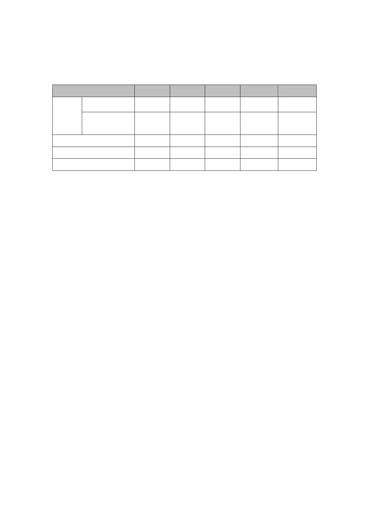
Options for protecting devices and cable specification
※Above data is subject to modification without notice.
Note: The above data is adapted to power cord ≤ 10 m. If power cord is >10 m, wire
diameter must be increased. The signal cable can be extended to 50 m at most.
1. Installation and Requirements
The swimming pool heater must be installed by a pool professional. End users are not
qualified to install the heater. Damage may occur to the heater or threaten the safety of the
user.
A. Installation
1) The swimming pool heater should be installed in a location with good ventilation;
2) The frame must be fixed by bolts (M10) to concrete foundation or brackets. The concrete
foundation must be solid and fastened; the bracket must be strong and antirust treated;
3) Don’t stack substances that will block air flow near inlet or outlet area, and no barrier within
20in behind the main heater, or the efficiency of the heater will be reduced or even haulted;
4) The heater needs an appended pump (Supplied by the user). The recommended pump
specification-flux: refer to Technical Parameter, Max. lift ≥10m;
5) When the heater is running, there will be condensation water discharged from the bottom.
Please hold the drainage nozzle (accessory) into the hole and attach it well, then connect a
pipe to drain the condensation water out.
B. Wiring