16
POWER READY or CONDENSATE ALERT LIGHT
CONDENSATE PUMP
EVAPORATOR FAN SWITCH and ON/OFF SWITCH
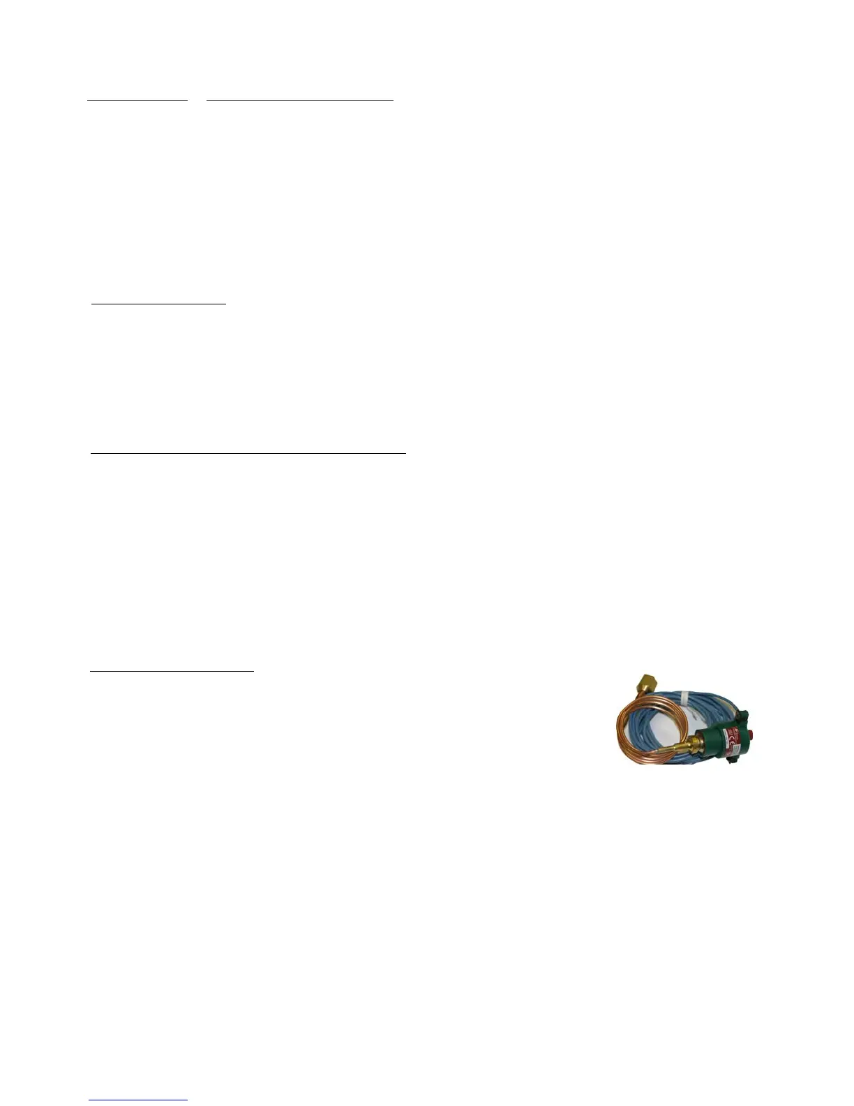
HIGH PRESSURE SWITCH
1. Disconnect unit from power/unplug power cord.
2. Remove attaching screws that secure the top panel.
3. Lift the top front panel about 6 inches to reveal the 2 wires that attach the light. The copper sensing tube for the
thermostat will provide some resistance. This is normal. However, do not kink the tubing.
4. Cut the 2 wires, pull the tinnerman clip away from the panel, and push the light out the front of the panel.
5. Push the new light through the panel and secure with the tinnerman clip.
6. Strip the insulation on the 2 cut wires in the unit. Attach one light wire to one of the just stripped wires and the
other light wire to the other just stripped wire. Secure with a wire nut or butt connector, and tape the nut and wire
together for extra strength.
7. Reinstall top panel and screws.
1. Disconnect power supply /remove plug from receptacle.
2. Remove right side panel.
3. Loosen nuts/bolts on pump mounting brackets.
4. Remove pump electrical cover (1 Phillips screw).
5. Remove & mark wires on low voltage and line voltage float switches; check terminals for tightness & suitability.
6. Replace condensate pump, reattach wires, replace cover & screw, reinstall attaching bolts, reinstall side panel.
1. Disconnect unit from power/unplug power cord.
2. Remove attaching screws that secure the top panel.
3. Lift the top front panel about 6 inches to reveal the switch and the 2 wires attached to it. The copper
sensing tube will provide some resistance. This is normal. However, do not kink the tubing.
Note: Mark the wire located on the center terminal and the wire on the outer terminal. Remove the wires by
pulling from the terminal.
4. With thumb and forefinger, squeeze the spring clips together that are on the LONG side of the switch and
push the switch out from the back, through the front panel.
5. Reinstall the new switch by pushing it through the panel from the front until it snaps into place.
6. Reattach wires, taking note of which wire was on the center terminal and which wire was on the outer terminal.
7. Reinstall top panel and attaching nuts.
1. Disconnect unit from power/unplug power cord.
2. Remove attaching screws from right side panel; remove panel.
3. Remove 4 screws from electrical access panel on lower back panel.
4. Remove nuts/bolts attaching the high pressure switch to the panel.
5. Mark location of two blue wires; remove from terminals.
6. Follow the tubing from the high pressure switch to the flare nut which attaches it to the
schrader access valve.
7. Remove flare nut from access valve. A small, DeMinimus release of refrigerant may occur when separating the
components. This is normal.
8. Pull the tubing, nut and wires through the panels, removing the switch assembly.
9. Reinstall, reversing the procedure.
High Pressure Switch