Do you have a question about the Norton Clipper TR 202 and is the answer not in the manual?
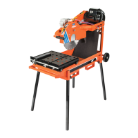
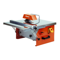
The TR 202 is a tile saw designed for durability and high performance in onsite wet cutting operations of a wide range of tiles. It is exclusively designed for cutting tiles with NORTON diamond disks, primarily on construction sites. The machine is not designed for cutting wood, metals, or other materials.
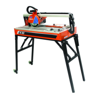
The TR 202 Saw is a robust and durable machine, featuring a frame made of aluminium and steel. Its folding stand with four legs ensures stability during cutting operations. The cutting head, an aluminium console, is precisely guided and supports the electric motor, guides, and blade guard. This head can be tilted to allow for angle cuts from 0 to 45 degrees.
The blade guard assembly is designed for a 200mm-diameter blade and is completely closed for maximum operator protection. The outside cover of the blade guard can be disassembled to access the blade, and its design also enhances visibility of the workpiece. The tightening of the fixing flange is achieved with a hexagonal head screw, which has a left-hand thread.
The machine is equipped with a water cooling system to ensure efficient wet cutting. This system includes a submersible mechanical water pump, a plastic suction pipe that delivers water from the water pan to the cutting head, and a removable large-capacity plastic water pan located under the cutting table. A nozzle on the disc casing ensures good distribution of water on the disc, reducing water loss and ensuring adequate cooling for the diamond blade. The water pump switches on automatically with the motor.
Powering the TR 202 is a single-phase 900W electric motor. The machine is operated via a switch with red and green buttons. The green button starts the machine, while the red button stops it and also functions as an emergency stop.
Before commencing work, operators must familiarize themselves with the working environment, including potential obstacles, floor firmness, necessary public thoroughfare protection, and the availability of help in case of accidents. The machine should always be sited on an even, firm, and stable base. Regular checks for correct blade mounting are crucial, and damaged or badly worn blades must be removed immediately as they pose a danger during rotation.
The material to be cut must be held securely in place on the table to prevent unexpected movement during cutting. Cutting should always be performed with the blade guard in position. Only NORTON diamond blades with a continuous rim should be fitted to the machine; using other tools can cause damage. Operators should carefully read blade specifications to select the correct tool for their application. Safety goggles (BS2092), ear protection, hand protection, and a dust mask (for dry cutting) are essential safety equipment.
For electrical safety, the TR 202 must always be turned off and disconnected from the main power source before any work is performed on it. All electrical connections must be secure to prevent contact of live wires with spray water or dampness. When using the TR 202 with water, proper earthing of the machine is imperative, and a qualified electrician should check connections if there is any doubt. In an emergency, the red button (0) on the switch should be pressed to stop the machine. If the TR 202 breaks down or stops without apparent reason, the main electricity supply must be switched off, and only a qualified electrician should investigate and remedy the fault.
Assembly of the TR 202 is straightforward. The legs are unfolded by lifting one side of the saw and extending the legs without wheels, then repeating for the other side with the wheels. The blocking arm is encased in the pin and tightened with a knurled button to prevent the feet from folding up. Handles are fixed to the side of the machine with screws and nuts for easier handling. The handle for the cutting head is also fixed with two screws. To enable machine use, the knurled button that secures the cutting head during transport must be unscrewed to release the head. The cable containing the water pipe is fixed along the rail of the cutting head. The pump is mounted in the water vat, and the drain plug is inserted. Transport wheels are assembled to the bottom of the feet opposite the handles using butterfly screws for easy movement.
For blade assembly, only NORTON blades with a diameter of 230 mm are to be used. All tools must be selected based on their maximum permitted cutting speed relative to the machine's maximum rotation speed. Before mounting a new blade, the machine must be switched off and isolated from the main electricity source. To assemble a new blade, three screws holding the outer cover of the blade guard are loosened with a crosshead screwdriver, and the cover is removed. The hexagonal nut (left-threaded) on the blade shaft, which secures the removable outer flange, is loosened with an 18 mm wrench. The outer flange is removed, and both flanges and the blade shaft are cleaned and inspected for wear. The blade is then mounted on the shaft, ensuring the correct direction of rotation (checked against the arrow on the blade guard) to prevent quick blunting. It is critical that the blade bore corresponds exactly to the blade shaft, as a cracked or damaged bore is dangerous. The outer blade flange is replaced, the hexagonal nut is tightened with the 18 mm wrench, and the outer cover of the blade guard is reattached and secured with the three holding screws.
Electrical connections require checking that the voltage/phase supply matches the motor plate information. The power supply must have a ground connection conforming to safety regulations, and connecting cables should have at least a 2.5mm² section per phase.
The angular guide of cut is fixed on the square, and the square is screwed onto the guide without overtightening. The unit is introduced into the groove on the side of the thrust, positioned for the desired cutting width, and then the screws are blocked. For the side guide of cut, it is placed on the table, tightened slightly with two knurled buttons, slipped to the desired remote position from the line of cut, and then the two knurled buttons are strongly tightened.
For the water cooling system, the TR 202 should be filled with clean water up to 1cm below the top edge of the water tray. It is crucial to ensure adequate water delivery to the blade, as insufficient supply can lead to premature diamond blade failure. The water pump must never run dry, so the water pan must always have enough water and be refilled as necessary. In frosty conditions, the water cooling system must be emptied.
To start the machine, connect it to the electric source and press the green button on the switch. To stop it, press the red button, which also serves as an emergency stop.
When operating, the user should face the TR 202, placing one hand on the cutting head and the other on the material to be cut to hold it against the material stops. Hands must always be kept away from the moving blade. The TR 202 is designed to cut materials with maximum dimensions of 600x600x20mm and a maximum weight of 15kg. Tools must be firmly seated before work. The right tools, as recommended by the manufacturer, should be selected based on the material, wet cut procedure, and required efficiency. The water pan must contain enough water. Only NORTON CLIPPER diamond discs should be used, as other tools may damage the machine. The engine should not be forced, as the machine is not designed for continuous use. A space of 2m in front of the machine and 1.5m around it is required for safe operation and maintenance.
To ensure long-term quality from cutting with the TR 202, a maintenance plan should be followed. This includes visual control of the whole machine (general aspect, water tightness) and cleaning of the machine, flange and blade fixing devices, motor cooling fans, water pan, motor housing, and water pump. Reachable nuts and screws should be tightened. These checks and actions are recommended before starting work, during tool changes, at the end of each day, or more often if required, during a failure, and after any damage.
All maintenance on the machine must be performed with the machine isolated from the electrical supply. The TR 202 uses life-lubricated bearings, meaning no lubrication is required. Thorough cleaning of the machine after each day of work, especially the water pump, water pan, motor, and blade flanges, will extend its lifespan.
For long-term storage, the machine should be completely cleaned, the water system emptied, and the water pump removed from the water tray and thoroughly cleaned. The storage site must be clean, dry, and maintained at a constant temperature. Before transporting the machine, the blade must always be removed, the water pan emptied, the cutting head secured on the rail using the knob, and the legs folded.
| Blade Diameter | 200 mm |
|---|---|
| Arbor Size | 25.4 mm |
| Voltage | 230 V |
| Motor power | 0.8 kW |
| No-load speed | 2950 rpm |