IQ-318/E/C Installation Manual — P/N 52864:J3 9/29/15 39
Fire/Security Applications Applications
4.6 Fire/Security Applications
4.6.1 General Operation
The control panel can be used as a combination Fire/Security system when installed and operated
according to the instructions in this section.
For security applications, program one or more monitor modules (listed for security applications)
with the
SECURITY Type Code, and wire as shown in Figure 4.6. Activating this type of module
lights the
SECURITY LED, and displays a security alarm condition on the control panel LCD display.
The panel sounder will sound until the Security alarm is acknowledged. You can also program
additional sounders or output devices to activate with the security alarm initiating device. The
SECURITY Type Code is designed to indicate an alarm as follows: (a) on an open or short circuit; or
(b) on a ±50% change in resistance value from the End-of-Line resistor value.
A tamper switch installed in the cabinet door will indicate a door tamper condition whenever the
door is open. If the control panel indicates a Security alarm, you can acknowledge, silence, and
reset the condition from the control panel.
When the system resets, a 30-second exit timer starts. During this time the tamper switch and all
Security alarms are ignored. There is no entrance delay timer.
For bypass of security zones, use the DISABLE routine (covered in the Status Change section of
the IQ-318/E Operations Manual) for Security type devices.
4.6.2 Installing a Security Tamper Switch
To wire the cabinet with a Security Tamper Switch kit model STS-200, refer to Figure 4.5:
1. Install the STS-200 Tamper Switch into the location shown in Figure 4.5. Push the switch
through the opening until it snaps into place.
2. Connect the STS-200 connector to J5 (Security Tamper) on the Control Panel. (As shown in
Figure 4.5, J5 is located on the circuit board, underneath the edge of KDM-R2.)
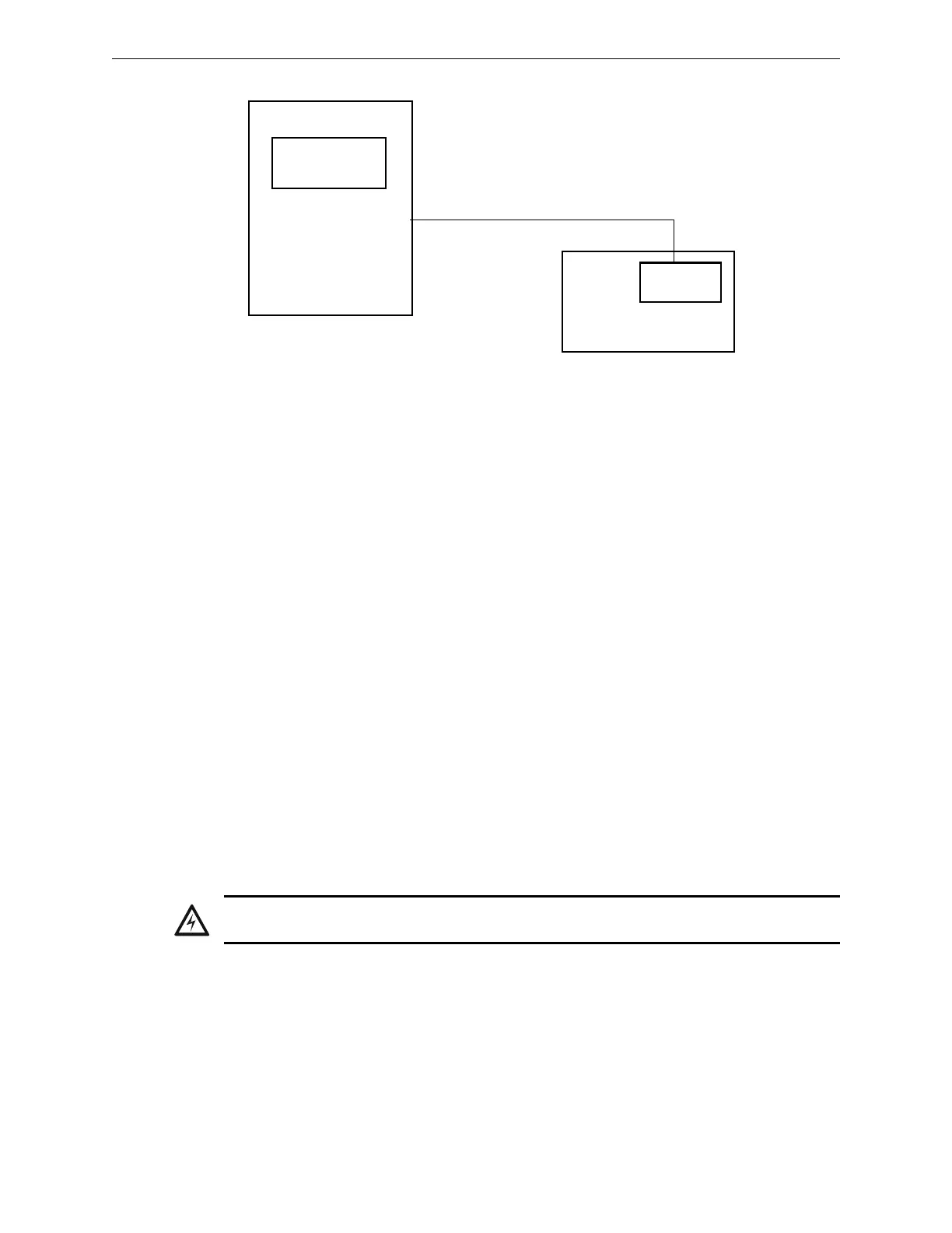
IQ-318/E
Protected Premises Unit
Compatible Receiving Unit
(see UDACT Manual or UDACT-2
Manual)
Telephone line and backup
UDACT
or UDACT-2
IQ-318/E
Figure 4.4 Typical Proprietary Fire Alarm Systems Wiring Connections
WARNING:
Damage can result from incorrect wiring connections.
 Loading...