10 IQ-318/E/C Installation Manual — P/N 52864:J3 9/29/15
System Overview System Components
2.1.2 Options
Refer to Section 2.2 “System Components” for descriptions of the various optional modules.
• Optional devices include:
UDACT/UDACT-2 Universal Digital
Alarm Communicator/Transmitter, and
ACM-8R remote relay module to increase
point capacity.
• Optional annunciators connected through
the EIA-485 interface allow remote
system monitoring.
2.1.3 System Limitations
System expansion must take into consideration the following:
1. The physical limitations of the cabinet configuration.
2. The electrical limitations of the system power supply.
3. The capacity of the secondary power source (standby batteries). (Note that batteries larger than
26 AH will require a separate battery backbox.)
2.2 System Components
2.2.1 Standard Equipment
The standard, factory-assembled IQ-318/E system includes the following components:
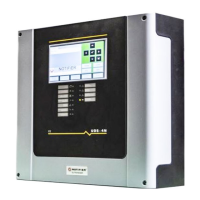
• The control panel with integral power supply, and cabinet. IQ318 (120V operation) or IQ318E
(220-240V operation), and CPS-24/E. IQ318/E is the “control panel” itself and the heart of the
system; it ships with a grounding cable, battery interconnect cables, and document kit. CPS-
24/E mounts directly on the control panel. The system ships pre-installed in its cabinet.
NOTE: The CPS-24/E is an integral part of the IQ318 and is not available separately.
• A primary display KDM-R2 keypad/display.
Batteries are ordered separately; refer to Appendix 6.3 “Calculating the Battery Requirements” for
system current-draw calculations.
Up to two option boards can be installed within the FACP’s cabinet; additional optional peripherals
can be mounted in auxiliary backboxes. Refer to Section 2.3, “Compatible Equipment” for
equipment listed for use with this FACP.
2.2.2 Control Panel Circuit Board
The control panel electronics are contained in IQ318 and its built-in power supply. The printed
circuit board incorporates a signaling line circuit (SLC) and the central processing unit; the power
supply has an integral battery charger. A keypad/display unit is installed over the power supply as
shown Figure 2.1. Wiring is shown in Figure 2.2, “IQ318 and Power-Supply: Wiring Connections”
and Figure 2.3, “IQ318 and Power-Supply: Jumpers, LEDs and Switches”.
 Loading...