12 IQ-318/E/C Installation Manual — P/N 52864:J3 9/29/15
System Overview System Components
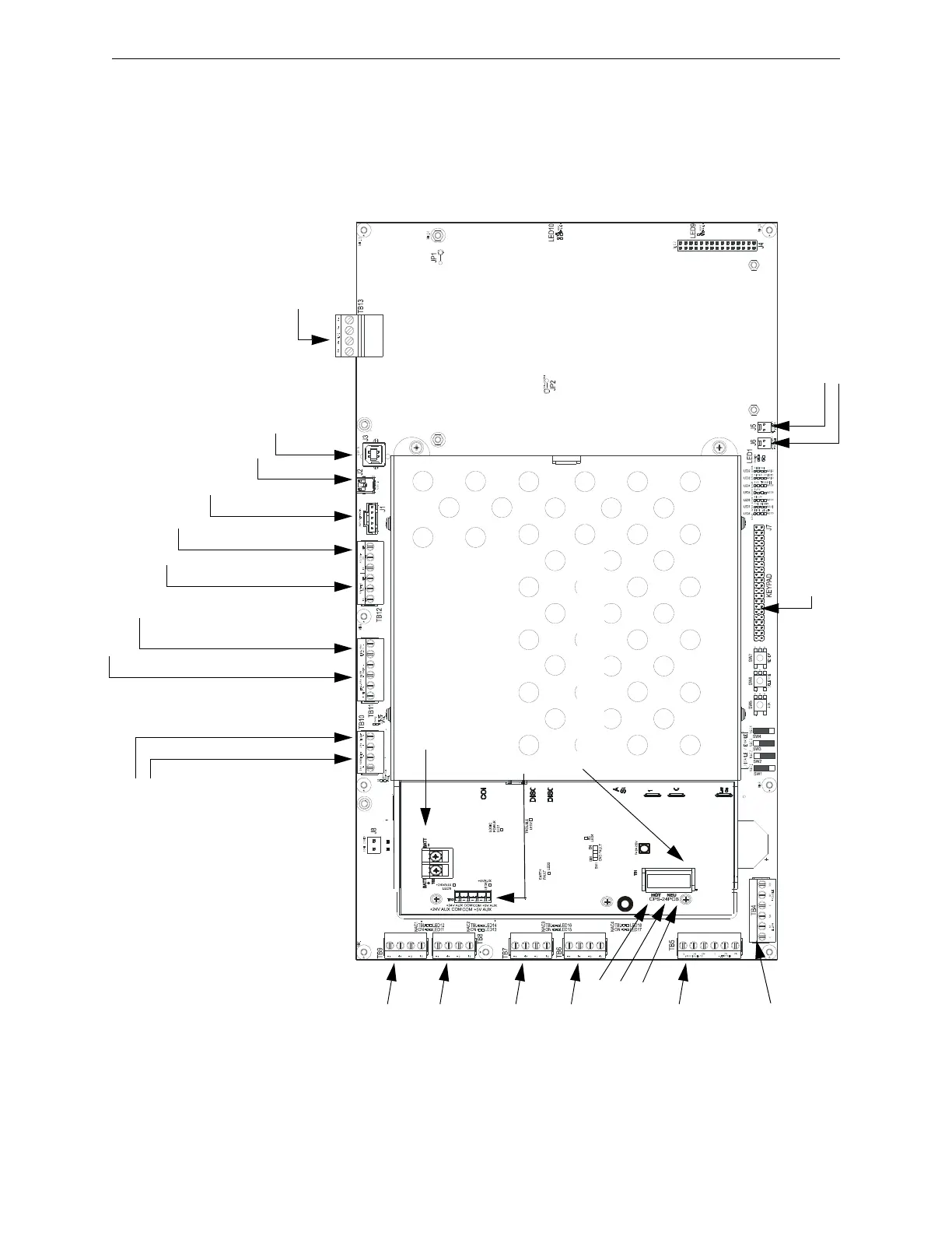
2.2.4 Circuit Board Components
The following three figures illustrate the location of the various connections, switches, jumpers and
LEDs on the IQ318 and its power supply. Figure 2.2 shows wiring connections; Figure 2.3 shows
jumpers, LEDs and switches. See Section 3 “Installation” for larger images and more details.
(Larger images are referenced on these drawings.)
TB13 - SLC Loop #1
(supervised, power-
limited)
(Figure 3.18)
TB11 - EIA-485 ACS Mode Connection (supervised)
TB11 - EIA-485 Terminal Mode Connection (supervised)
(Figure 3.14 on page 28)
TB10 - DC Power
(24 VDC power-limited)
Resettable
Non-resettable
(See Figure 3.6 on page 22)
TB12 - EIA-232 Printer Connection (Figure 3.15 on page 33)
TB12 - EIA-232 PC/Terminal Connection (CRT)
(Figure 3.16 on page 31)
J1 - Network/Service Connection (NUP)
(power-limited, supervised)
J2 - USB A VeriFire Tools Connection
J3 - USB B VeriFire Tools Connection
TB8 - NAC#2
All NAC Circuits: power-
limited, supervised
(Figure 3.9 on page 24)
TB9 - NAC#1
TB7 - NAC#3
TB6 - NAC#4
Output Relays - power-limited only if connected to a power-limited
source. (See Figure 3.11 on page 25 for details.)
TB5 -
Supervisory Relay
Security Relay
TB4 -
Alarm Relay
Trouble Relay
J5 - Security Tamper Switch
J6 - Auxiliary Trouble Input
J7 - KDM-R2
Connection
CPU320-KAPS-
Figure 2.2 IQ318 and Power-Supply: Wiring Connections
TB3 - Battery Connection
(over-current protected, non-power-limited)
TB1 - AC Power Connection (non-
power-limited)
Hot
Neutral
Earth
Ground
(+) (-)
TB2 - Secondary Power Auxiliary Outputs
(power-limited)
 Loading...