Programming Options NEC Power-limited Wiring Requirements
18 FCPS-24S PN 51977:C1 08/06/03
SECTION 3 Programming Options
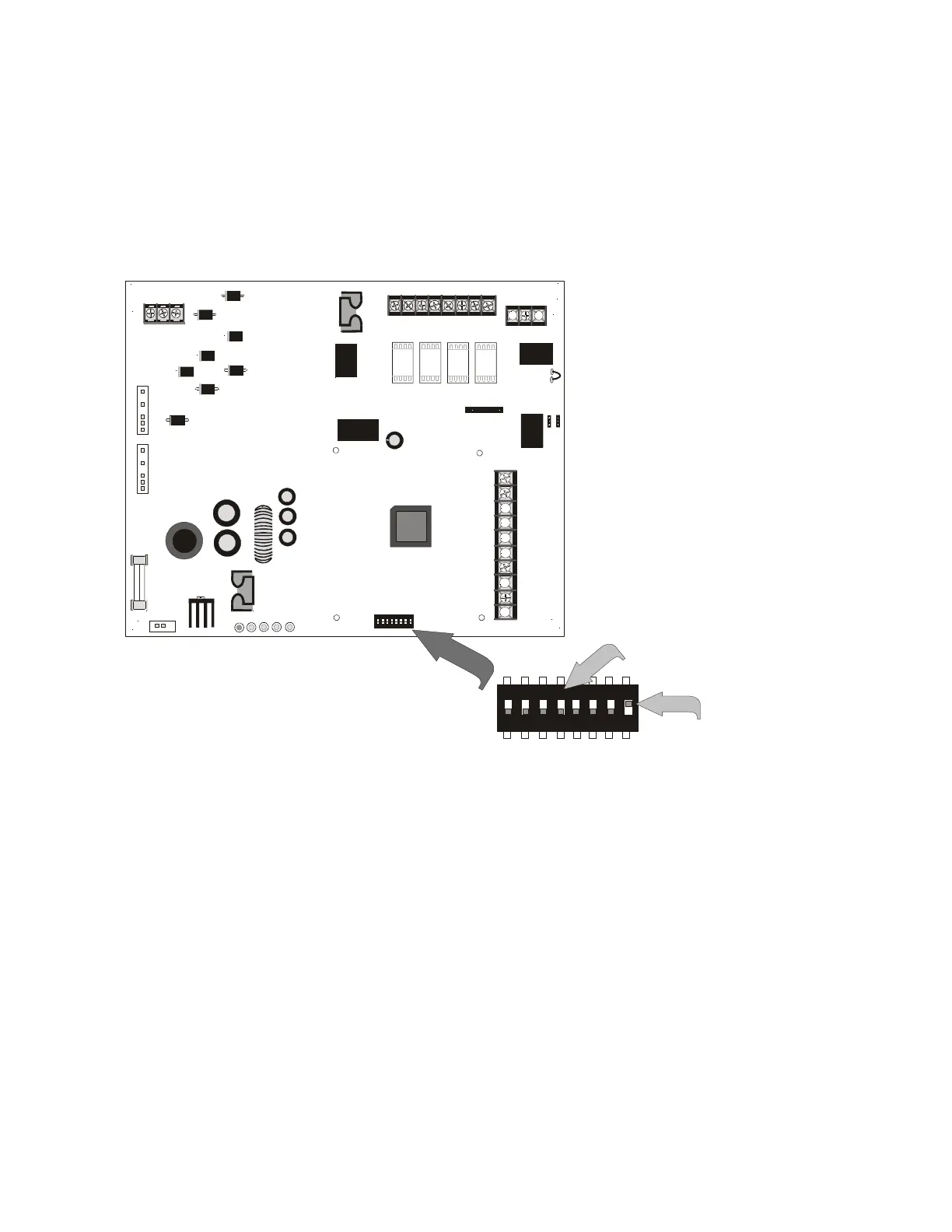
This section describes the programming options available via DIP switch settings. The
FCPS can be field programmed using option DIP switch SW1 which is located in the
lower center of the circuit board. Refer to the following illustration for switch location
and DIP switch placement in the ON and OFF positions.
Important: Change DIP switch settings only when all power (AC & DC) is removed.
ON
1 2 3 4 5 6 7 8
1 2 3 4 5 6 7 8
ON
TB1
J2
TRANSFORMER 2
TRANSFORMER 1
J1
F1
JP4
30V
15A
SW1
TB4
JP3
J3
TB5
TB2
JP1
JP2
+ -
EARTH NEUT HOT
OUT4
- NAC4 +
OUT3
- NAC3 +
OUT2
- NAC2 +
OUT1
- NAC1 +
8 7 6 5 4 3 2 1
3 2 1
10
9
8
7
6
5
4
3
2
1
AUX -
IN2-
IN2+
OUT1-
OUT1+
IN1-
IN1+
SYNC IN -
SYNC IN +
AUX +
NO NC
AUX TBL
COM
BATT ERY
AC
AC/
BATT
CHGR
GND
FLT
NAC
TRBL
Switches 1 through 7 shown
in OFF (Open) position
Switch 8 shown in ON
(Closed) position
Figure 3.1 Field Programming DIP Switches
24fsswitc.cdr
www.PDF-Zoo.com