Page 4 of 6 — DN-6720 • 08/23/04
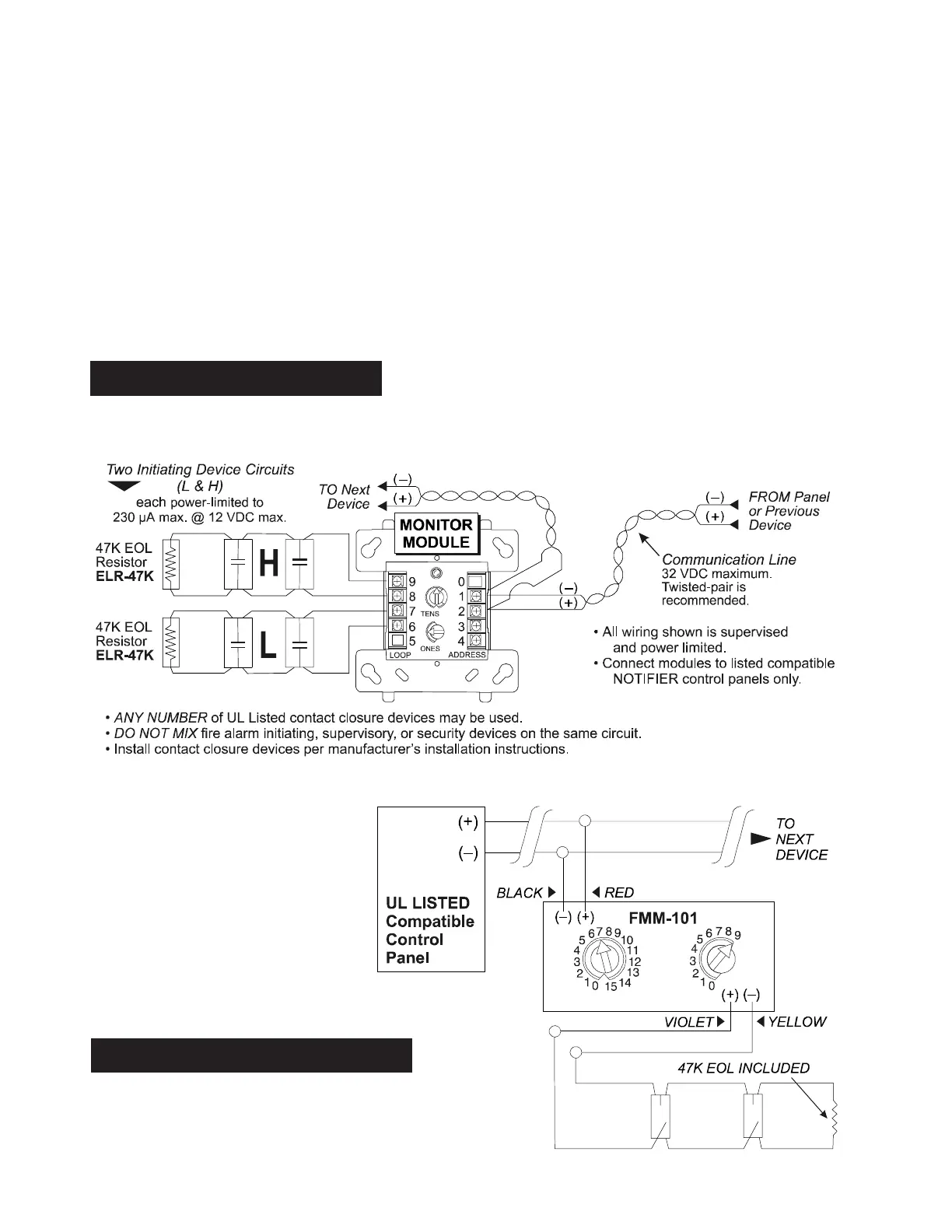
Fig. 2 FMM-101: Typical two-wire Style B
initiating device circuit configuration.
6720wir1.wmf
WIRING DIAGRAM: FMM-101
WIRING DIAGRAMS
The following wiring diagrams are included:
1) FDM-1, typical dual two-wire Style B initiating device circuit configuration.
2) FMM-101, typical two-wire Style B initiating device circuit configuration.
3) FMM-1, typical two-wire initiating circuit configuration, NFPA Style B.
4) FMM-1, typical four-wire fault-tolerant initiating circuit configuration, NFPA Style D.
5) FMM-1, typical two-wire initiating circuit configuration for security systems
(with alarm versus short capability).
6) FZM-1, interface two-wire conventional detectors, NFPA Style B.
7) FZM-1, interface two-wire conventional detectors, NFPA Style D.
8) FRM-1, relay control module used to disconnect a power supply.
Fig. 1 FDM-1: Typical dual two-wire Style B
initiating device circuit configuration.
WIRING DIAGRAM: FDM-1
6822wir1.wmf