DN-6720 • 08/23/04 — Page 5 of 6
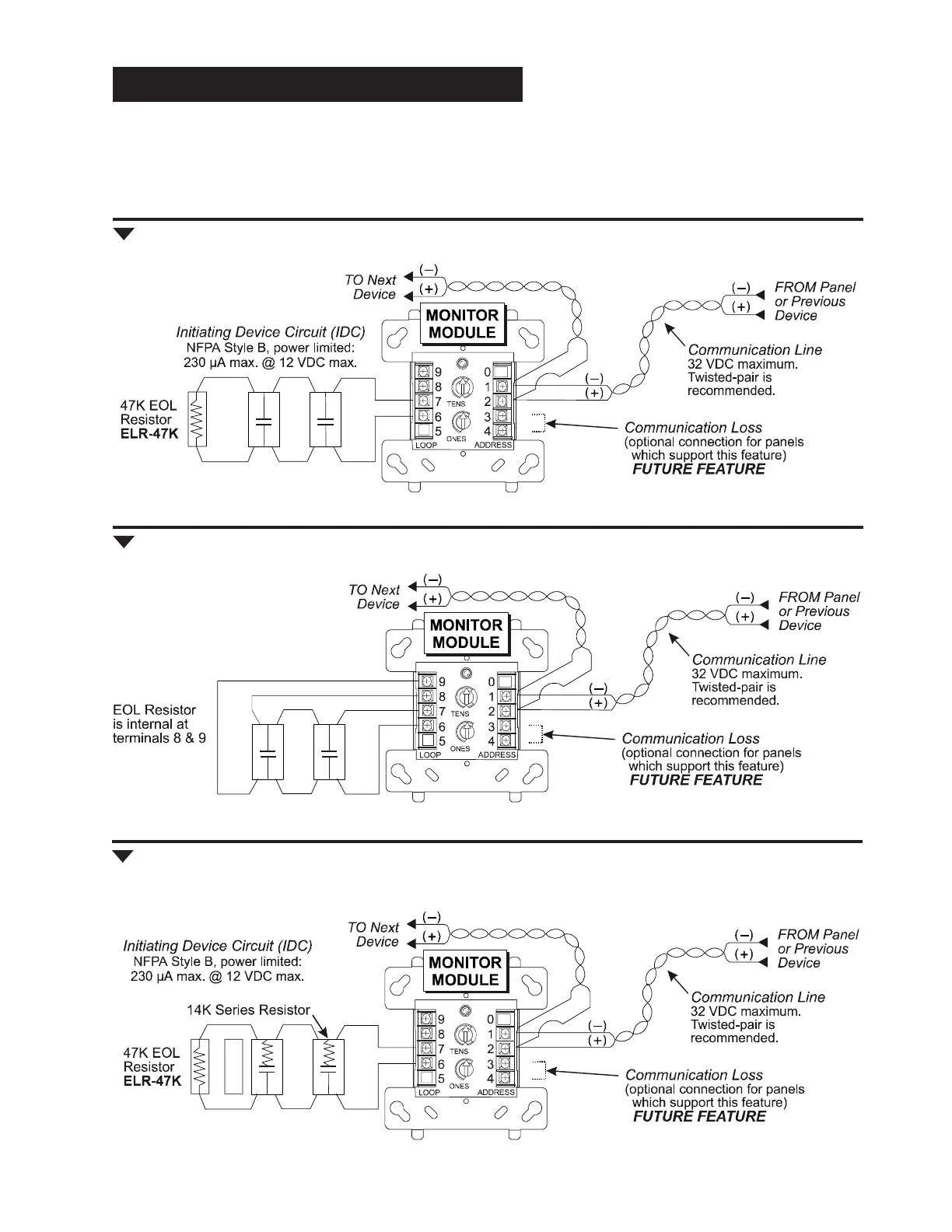
Fig. 3 FMM-1: Typical two-wire initiating device circuit configuration, NFPA Style B.
• Connect modules to listed compatible NOTIFIER control panels only.
• All wiring shown is supervised and power limited.
• Install contact closure devices per manufacturers’ installation instructions.
• Any number of UL-listed contact closure devices may be used.
• DO NOT MIX fire alarm initiating, supervisory, or security devices on the same circuit.
WIRING DIAGRAMS THIS PAGE: FMM-1
Fig. 4 FMM-1: Typical four-wire fault-tolerant initiating circuit configuration, NFPA Style D.
Fig. 5 FMM-1: Typical two-wire initiating circuit configuration for security systems
(with alarm versus short capability).
6720wir2.wmf
6720wir3.wmf
6720wir4.wmf