PAGE - 26 Installation and operating manual UDS-4
NOTIFIER ITALIA Doc. M--203.1-UDS4N-ENG Rev A. 1 UDS-4_manu
7 - UDS-4N PANEL WALL MOUNTING INSTRUCTIONS
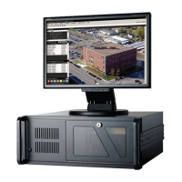
The panel must be installed on the wall in such a way as to allow clear visibility of the display and easy access for the
operator. For example, a height of approximately 1.5 m allows optimal viewing of the display.
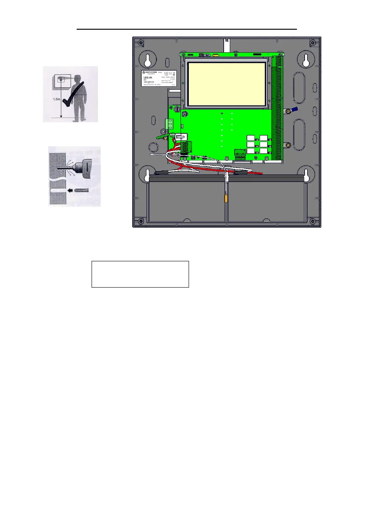
The front panel can be opened by unscrewing the four screws securing the cover.
Cable connections:
- Cables for connection to alarm detection devices, auxiliary devices and the power supply network can be fed
into the UDS-4N by drilling holes, running the cables alongside the terminal blocks and providing a suitable
buffer.
- For these connections, use cable with a minimum cross-section of 0.5 mm2 and maximum length = 100 m.
Network connection
- The 230Vac power supply cable must be fixed inside the device with a suitable cable clamp.
- A disconnecting means must be provided for the 230Vac power cable outside the UDS (contact separation: 3
mm min.). The disconnecting means must be easily accessible, omnipolar or capable of disconnecting the phase.
- An external 10A thermal-magnetic protection or equivalent fuse must also be installed.
- When wiring cables from the outside, prevent the safety extra-low voltage conductors from coming into contact
with hazardous voltage points, and the ends of the stranded conductors must not be soft-soldered at points
where the conductors are subject to contact pressure.
- The cable entries on the upper and lower sides of the enclosure must be provided with a pipe/casing connection.
In addition, the fitting material must have a flammability class of HB or higher.
- The electrical connection to the primary network must comply with the applicable national regulations.
- The 230Vac mains power cable should preferably run close to the relevant terminal block.
- Connection to the 230Vac power supply is via a three-conductor cable (phase - neutral - earth).
- The earth conductor coming from the mains must be terminated on terminal strip CN1. The conductor must be
secured to the cabinet with a cable tie so that it cannot be accidentally pulled out of the terminal block.
The connection of the power supplies must be carried out in accordance with the following steps:

 Loading...