10 HS-NCM Installation Document — P/N 54014:B2 04/25/2014
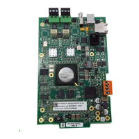
Figure 7 The HS-NCM-W
Switch Functions: Ground Fault Detection.
For UL 864 applications, enable ground fault
detection by setting EF switches “on”:
SW4.1 for Channel A, and SW4.2 for Channel B.
Correct configuration depends on your network
design; for an explanation of design concepts, refer to
the High-Speed Noti•Fire•Net™ Manual.
Ground faults are detected when the resistive value
reaches 0 ohms.
Ground Fault monitoring is performed by the FACP
associated with the HS-NCM.
TB4-1 CH-A (+) Channel-A Driver/Receiver
TB4-2 CH-A (-) Channel-A Driver/Receiver
TB5-1 CH-B (+) Channel-B Driver/Receiver
TB5-2 CH-B (-) Channel-B Driver/Receiver
Table 2 NOTI•FIRE•NET™ Connections: HS-NCM-W
NOTE: Ground fault detection must be enabled for UL 864 applications and for ULC applications.
Note: Wiring from the HS-NCM-W that is installed outside the building:
• Cannot exceed 1000m (3280 ft.).
• Must be in conduit and is to be buried in a trench separate from any power lines.
• Cannot cross any power lines.
From previous
node, Port B
To next node,
Port A
HS-NCM-w-connex.wmf
SHLD
SHLD
SHLD
SHLD
– +
– +
– +
– +
TB4
CH. A
TB5
CH. B
TB4
CH. A
TB5
CH. B
hs-ncm-w-switches.wmfr
Figure 8 HS-NCM-W Switches
Ground Fault
Detection Switches